Transmission apparatus

a technology of transmission apparatus and transmission device, which is applied in the direction of data switching network, frequency-division multiplex, instruments, etc., can solve the problems of not being able to greatly reduce the capital cost and running cost of an optical network for transmitting ip signals, and the management of networks at the transmission control protocol/. problems, to achieve the effect of reducing the capital cost and running cost of an optical network

Inactive Publication Date: 2005-02-01
FUJITSU LTD
View PDF6 Cites 27 Cited by
  • Summary
  • Abstract
  • Description
  • Claims
  • Application Information

AI Technical Summary

Benefits of technology

An object of the present invention is, in view of the above problem, to provide a transmission apparatus able to greatly reduce the capital costs and running costs of an optical network for transmitting IP signals.

Problems solved by technology

In other words, they can only manage networks at the transmission control protocol / IP (TCP / IP) layers.
As will become evident later, however, in the past, no technique has been proposed enabling entire networks to be integrally managed by having single transmission apparatuses perform processing for the SONET / SDH / WDM layers and the TCP / IP layers.
In the final analysis, there has therefore been the problem that it has not been possible to greatly reduce the capital costs and running costs of an optical network for transmitting IP signals.

Method used


Image

  • Transmission apparatus
  • Transmission apparatus
  • Transmission apparatus

Examples


embodiments

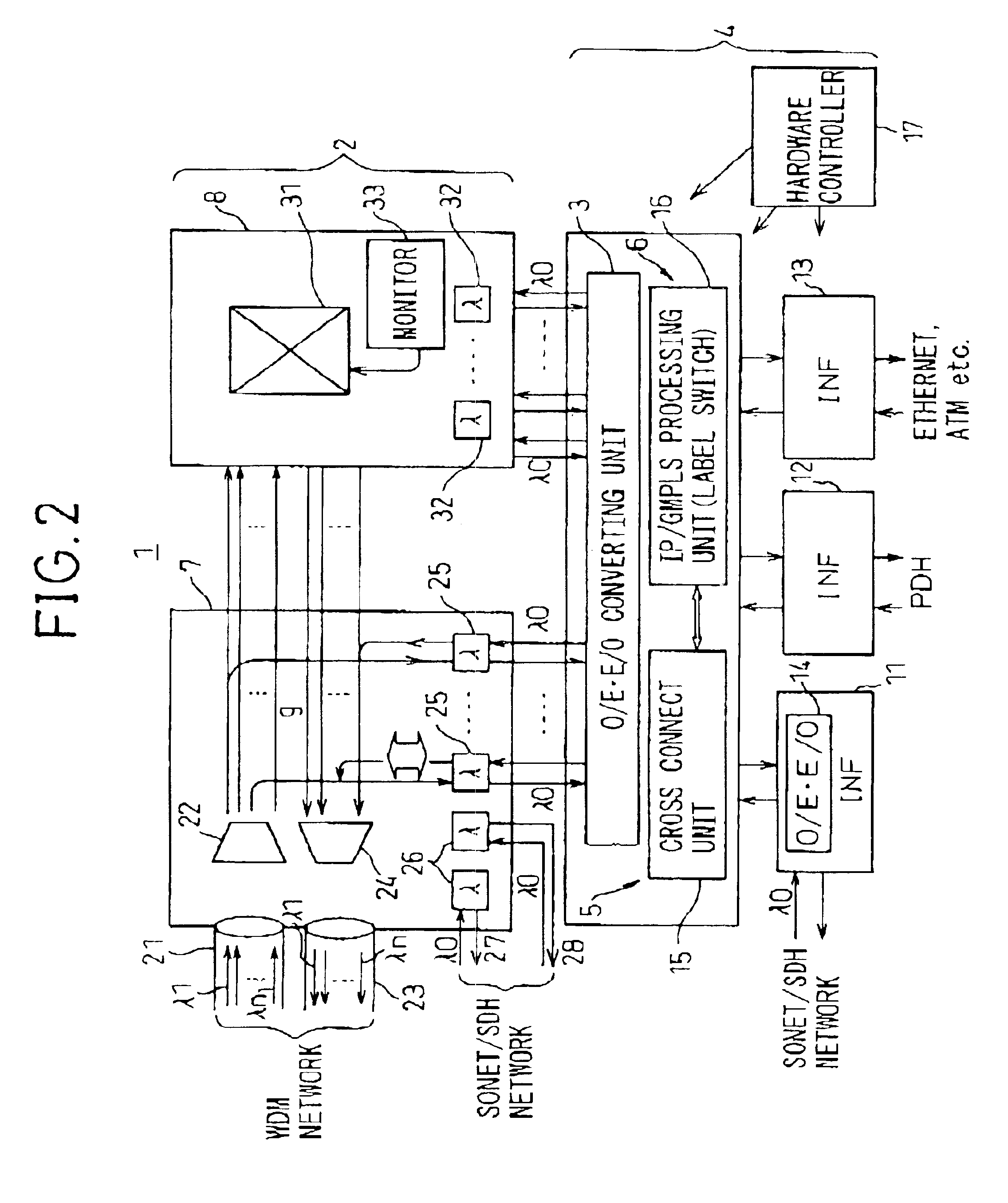
FIG. 2 is a view of a transmission apparatus of an embodiment of the present invention.

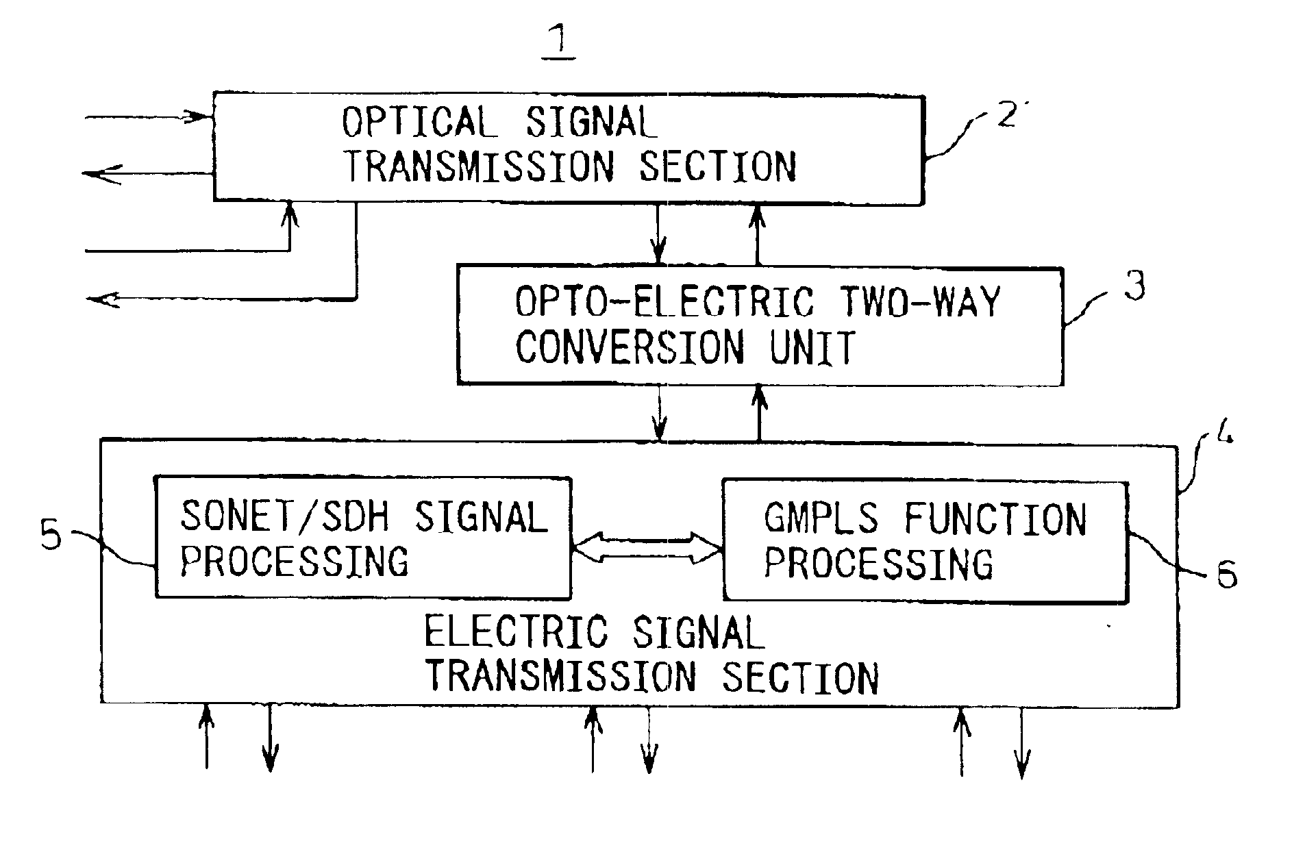
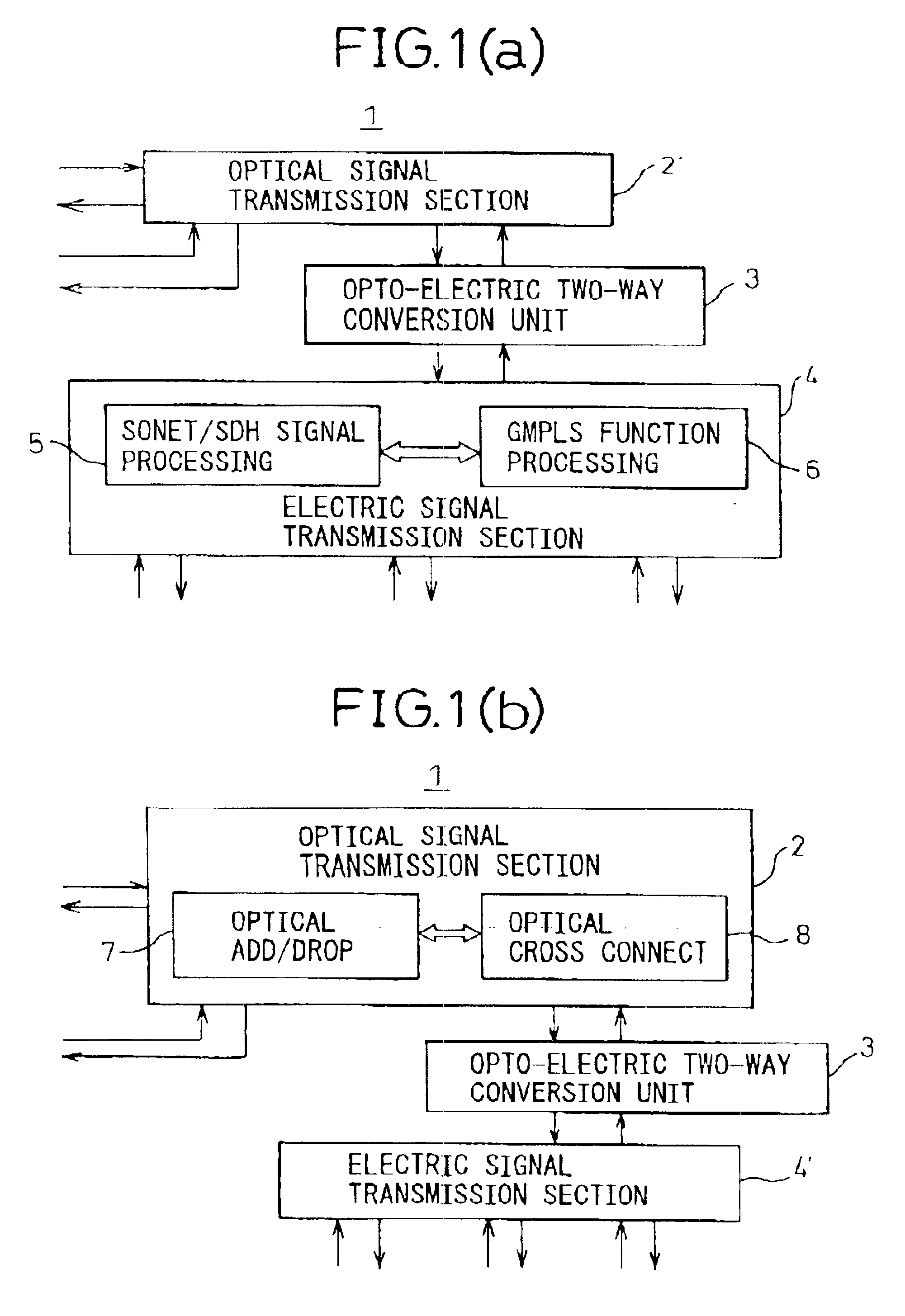
As already explained, the present invention will be described with reference to a configuration employing the optical signal transmission section 2 of FIG. 1(b) as the optical signal transmission section 2′ of FIG. 1(a). This configuration is shown in FIG 2. Note that throughout the figures, similar components are assigned the same reference numerals or symbols.

In FIG. 2, the top part shows the already explained optical signal transmission section 2, while the bottom part shows the electrical signal transmission section 4. Between these is provided an opto-electric two-way (O / E-E / O) conversion unit 3. FIG. 2, however, shows an example where this O / E-E / O conversion unit 3 is provided at the electrical signal transmission section 4 side.

First, looking at the optical signal transmission section 2 at the top part of the figure, this section is comprised of an optical add / drop function unit 7 and an op...


PUM


Abstract

A transmission apparatus for coupling an optical signal transmission section and an electrical signal transmission section through an opto-electric two-way conversion unit, where the electrical signal transmission section is comprised of a SONET / SDH signal processing function unit and a generalized multi protocol label switching (GMPLS) function processing function unit cooperating with that function unit and where the optical signal transmission section is comprised of an optical add / drop function unit for transferring an optical signal with the electrical signal transmission section through the conversion unit and an optical cross-connect function unit for switching paths in wavelength units of the optical signal with the electrical signal transmission section, whereby the capital cost and running costs of an optical network for transmitting an IP signal can be greatly reduced.

Description

BACKGROUND OF THE INVENTION1. Field of the InventionThe present invention relates to a transmission apparatus, more particularly relates to a transmission apparatus provided with a synchronous optical network / synchronous digital hierarchy (SONET / SDH), wavelength division multiplexing (WDM), or other interfaceAs such transmission apparatuses, in general, there are add-drop multiplexer (ADM) apparatuses, cross-connect apparatuses, optical ADM (OADM) apparatuses, optical cross-connect (OXC) apparatuses, etc. Further, in the present invention, the transmission apparatuses include transmission apparatuses for adding / dropping, cross-connecting, or switching plesiochronous digital hierarchy (PDH) signals, asynchronous transfer mode (ATM) signals, and Ethernet signals. Further, the present invention may also include all sorts of transmission apparatuses (communication apparatuses) for transmitting Internet protocol (IP) signals2. Description of the Related ArtConventional SONET / SDH transmis...

Claims


Application Information

Patent Timeline
Patent Type & Authority Patents(United States)
IPC IPC(8): G02B6/28H04J14/02H04B10/20H04B10/02H04L12/56H04J3/00H04L12/43H04L12/42H04L12/427H04B10/27H04B10/275H04B10/291H04L12/701
CPCH04J14/0201H04J14/0241H04L12/43H04J14/0227H04J14/0283H04J14/0284H04J14/0286H04J14/029H04J14/0291H04J14/0294H04J14/0295H04J2203/0042H04J2203/006H04J2203/0096H04L2012/5652H04L2012/5665
Inventor NOTANI, MORIHITO
Owner FUJITSU LTD
Why Eureka
Try Eureka