
Electric-motor driven parking brake, particularly for a motor vehicle

a technology for parking brakes and motor vehicles, which is applied in the direction of brake systems, friction linings, transportation and packaging, etc., can solve the problems of large unit volume of parking brakes, low efficiency of parking brakes, and inability to release brakes, and achieve the effect of increasing cable forces

Inactive Publication Date: 2005-02-08
SIEMENS AG
View PDF19 Cites 11 Cited by
  • Summary
  • Abstract
  • Description
  • Claims
  • Application Information

AI Technical Summary

Benefits of technology

The drive links, consisting of such a cam disk or gate guide, as applicable, and such an actuation element, exhibit very low frictional losses, so that the parking brake has a high level of efficiency.
Preferably, an additional leverage will be introduced between the actuation element and the brake-actuating linkage, so that the cam disk or gate guide can make a longer cable movement or achieve greater cable forces.

Problems solved by technology

In addition, suitable measures must be provided to ensure that, after the brake has been pulled on and the motor switched off, the brake cannot be released as a result of an unintended backward movement of the brake cable.
However, a consequence of this is that the parking brake has a low efficiency because such a spindle drive has high frictional losses and, depending on its arrangement, a gearbox which is subject to further losses must generally be inserted between the motor and the spindle.
Furthermore, such parking brakes have a large unit volume, because a larger motor is required due to the low efficiency.
A further disadvantage consists in the fact that the large motor means that the current required cannot always be supplied by the vehicle's electrical system.

Method used


Image

  • Electric-motor driven parking brake, particularly for a motor vehicle
  • Electric-motor driven parking brake, particularly for a motor vehicle
  • Electric-motor driven parking brake, particularly for a motor vehicle

Examples


Embodiment Construction

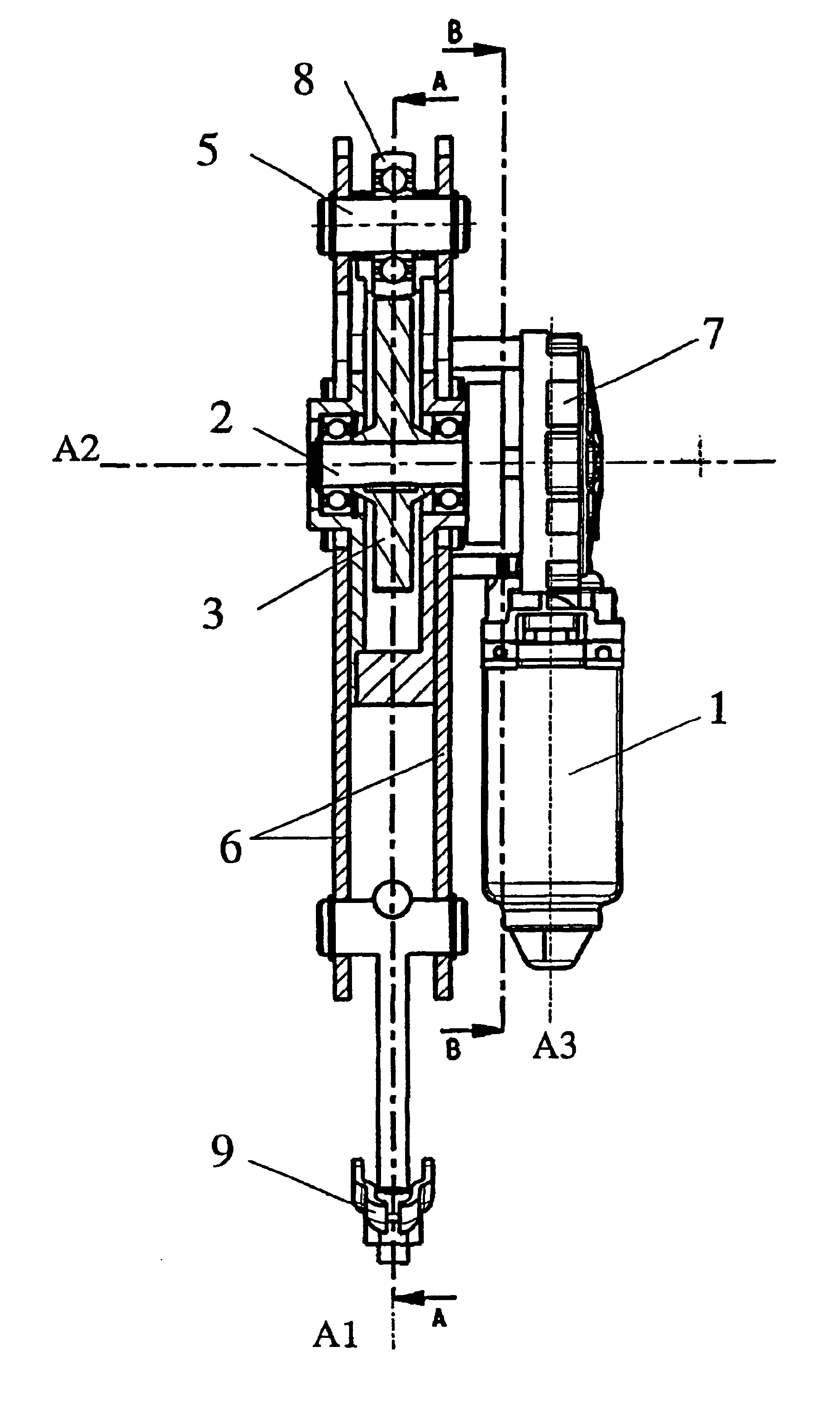
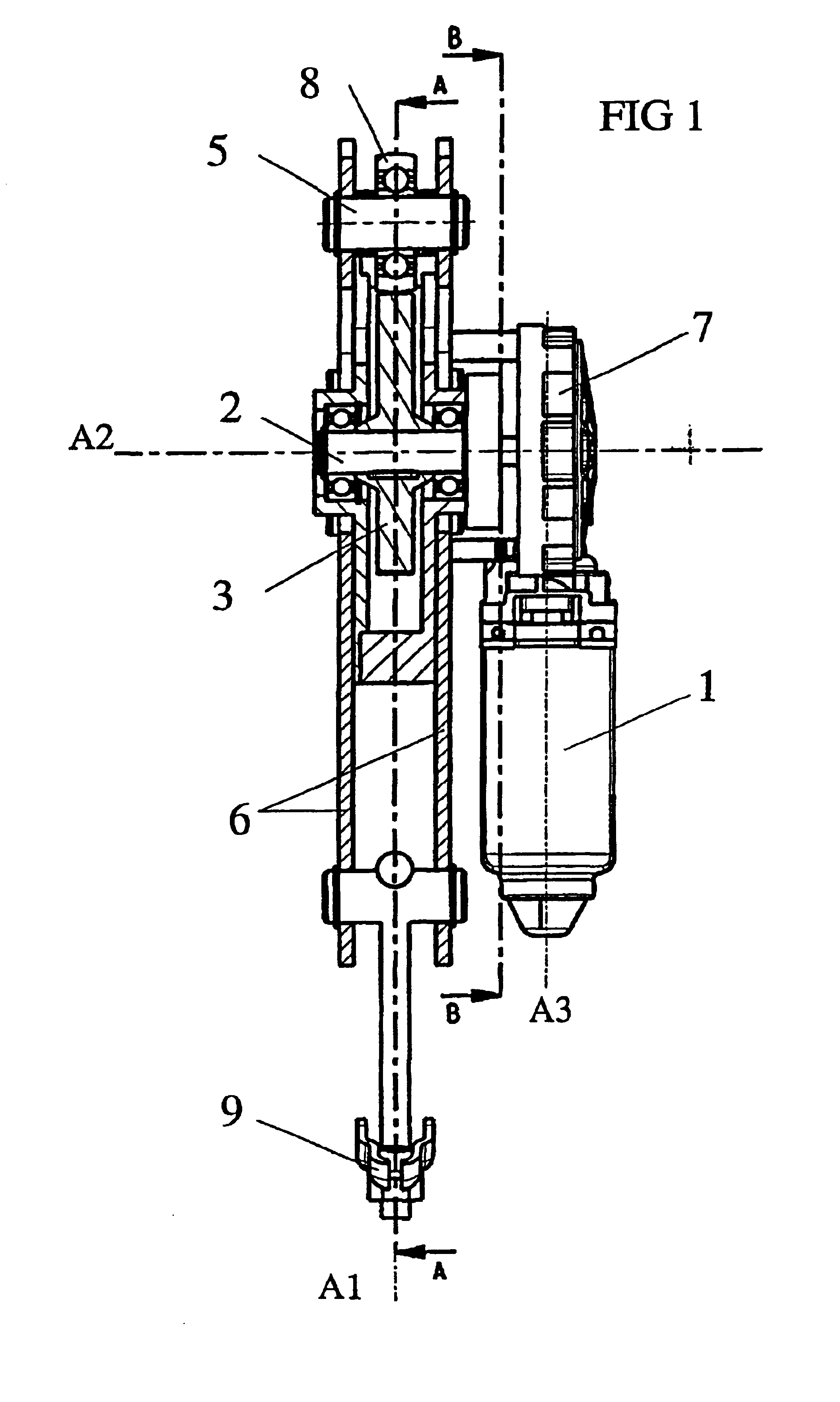
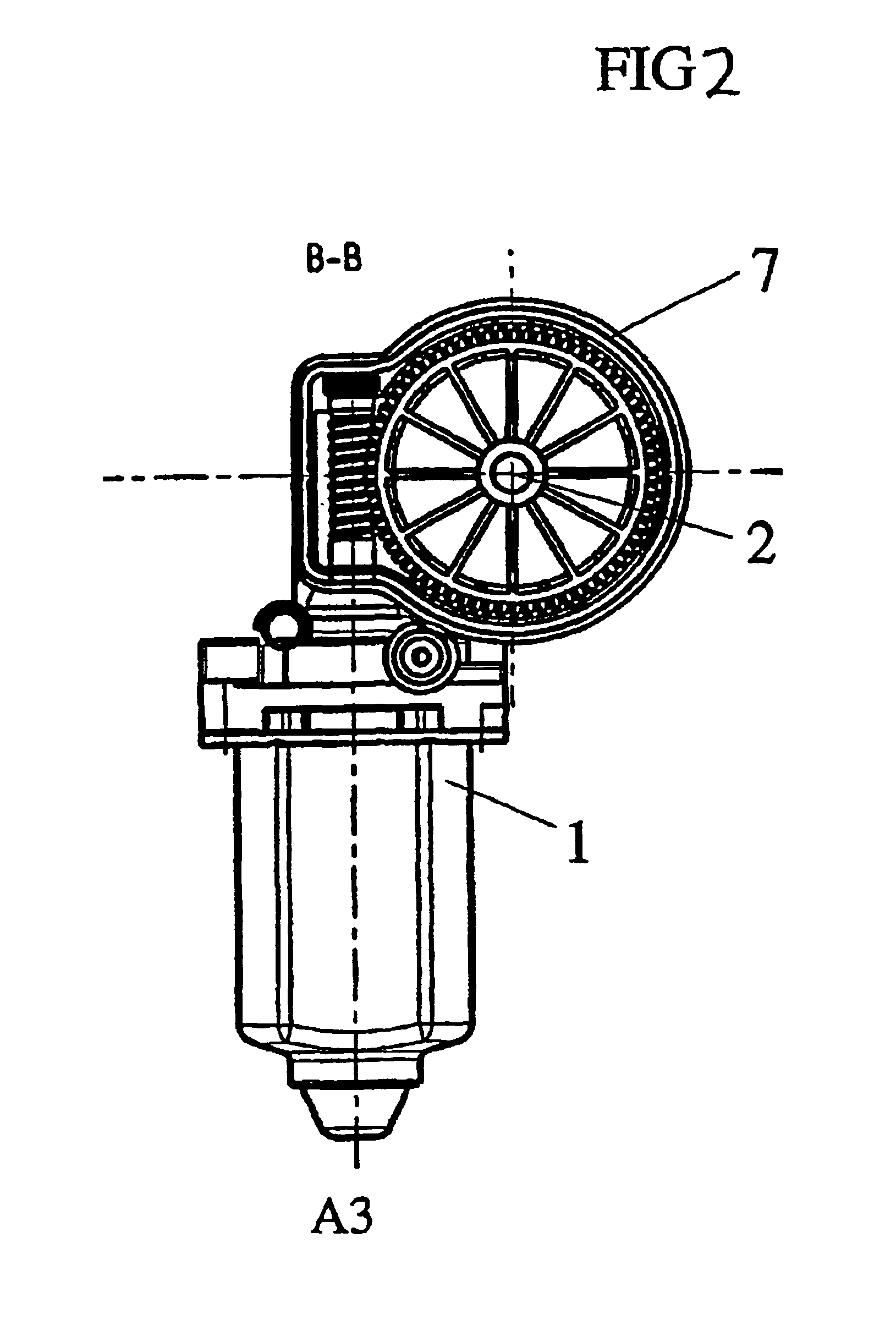
In an exemplary embodiment, a parking brake has an electric brake actuation motor 1, in particular a commutator motor. Via a worm drive 7, the electric motor 1 drives a brake-actuating output shaft 2 which runs perpendicularly to the motor axis A3, and hence to the motor shaft (see FIGS. 1 and 2). The brake-actuating output shaft 2 runs along a second axis A2.

A radial cam disk or gate guide 3 is mounted so that it is concentric with the brake-actuating output shaft 2, and has a height profile 3.1 in the radial direction, which defines a surface F around the perimeter of the cam disk or gate guide 3 (see FIG. 3).

A crossbeam-type axial actuation element 5 with a roller 8 is arranged so that it can move along a first axis A1, which is oriented perpendicularly to the second axis A2 and parallel to the motor axis A3. The roller 8 rests on the surface F. When the cam disk or gate guide 3 is rotated, the roller 8 is guided along the surface F, causing the actuation element 5 to execute a t...


PUM


Abstract

A parking brake is disclosed, comprising a brake-actuating electric motor (1), a brake actuating output shaft (2) driven by said electric motor and extending along a second axis (A2), a brake-actuating linkage (4) that is adjustably arranged parallel to a first axis (A1) that substantially extends perpendicularly to the second axis (A2), and a drive connection from the brake-actuating output shaft (2) to the brake-actuating linkage (4). The drive connection is configured in the form of a cam-type cam disk or gate guide (3) that translates the rotation of the brake-actuating output shaft (2) into a translational movement of the brake-actuating linkage (4) through an adjusting element (5) that is guided along a surface (F) of the cam disk or gate guide 93) forming a radial profile. The motor axis (A3) of the brake-actuating electric motor (1) extends substantially perpendicular to the second axis (A2).

Description

TECHNICAL FIELD OF THE INVENTIONThe invention relates to an electric-motor driven parking brake, particularly for a motor vehicle.BACKGROUND OF THE INVENTIONElectric-motor driven parking brakes in motor vehicles are intended to replace the mechanical handbrake lever, actuated by muscle power. For this purpose, the electric-motor driven parking brake must be capable of building up the required brake actuation force in the brake cable within a very short time using the current available from the vehicle electrical system, while having the most compact dimensions possible. In addition, suitable measures must be provided to ensure that, after the brake has been pulled on and the motor switched off, the brake cannot be released as a result of an unintended backward movement of the brake cable.Known electric-motor driven parking brakes have an electric motor which drives a spindle gearbox. The spindle gearbox converts the rotary movement of the electric motor into a translational movement...

Claims


Application Information

Patent Timeline
Patent Type & Authority Patents(United States)
IPC IPC(8): B60T13/74B60T7/02B60T7/10B60T13/00F16D65/34F16D65/14F16D65/28
CPCB60T7/107B60T13/741F16D65/28B60T13/746F16D2125/36F16D2121/24
Inventor BAIER-WELT, CHRISTIANROOS, STEPHAN
Owner SIEMENS AG
Learn More