
Oil separator

a technology of oil separator and separator shaft, which is applied in the direction of crankcase ventillation, machine/engine, mechanical equipment, etc., can solve the problems of imbalance in discharge efficiency, inability to efficiently collect oil mist, etc., and achieve the effect of convenient supply

Active Publication Date: 2017-03-21
AISIN SEIKI KK +1
View PDF22 Cites 1 Cited by
  • Summary
  • Abstract
  • Description
  • Claims
  • Application Information

AI Technical Summary

Benefits of technology

This configuration ensures efficient recovery of oil mist regardless of particle diameter differences, balancing collection and discharge efficiencies across the oil separation units.

Problems solved by technology

Since oil mist particles having different particle diameters are collected by the respective cyclones in this way, there has been a problem that differences appear in the collection efficiencies of the cyclones, and it is not possible to efficiently collect oil mist.
Also, with the oil separator disclosed in Patent Document 1, the blow-by gas discharge opening is located in the end portion on the side opposite to the gas introducing opening, and therefore imbalance arises in the discharge efficiency when blow-by gas from which oil mist has been separated is sucked out and discharged from the respective cyclones.
This gives rises to a problem of poor discharge efficiency for the oil separator overall.

Method used


Image

  • Oil separator
  • Oil separator
  • Oil separator

Examples


Embodiment Construction

[0019]An embodiment of the present invention will be described below with reference to the drawings.

Basic Configuration

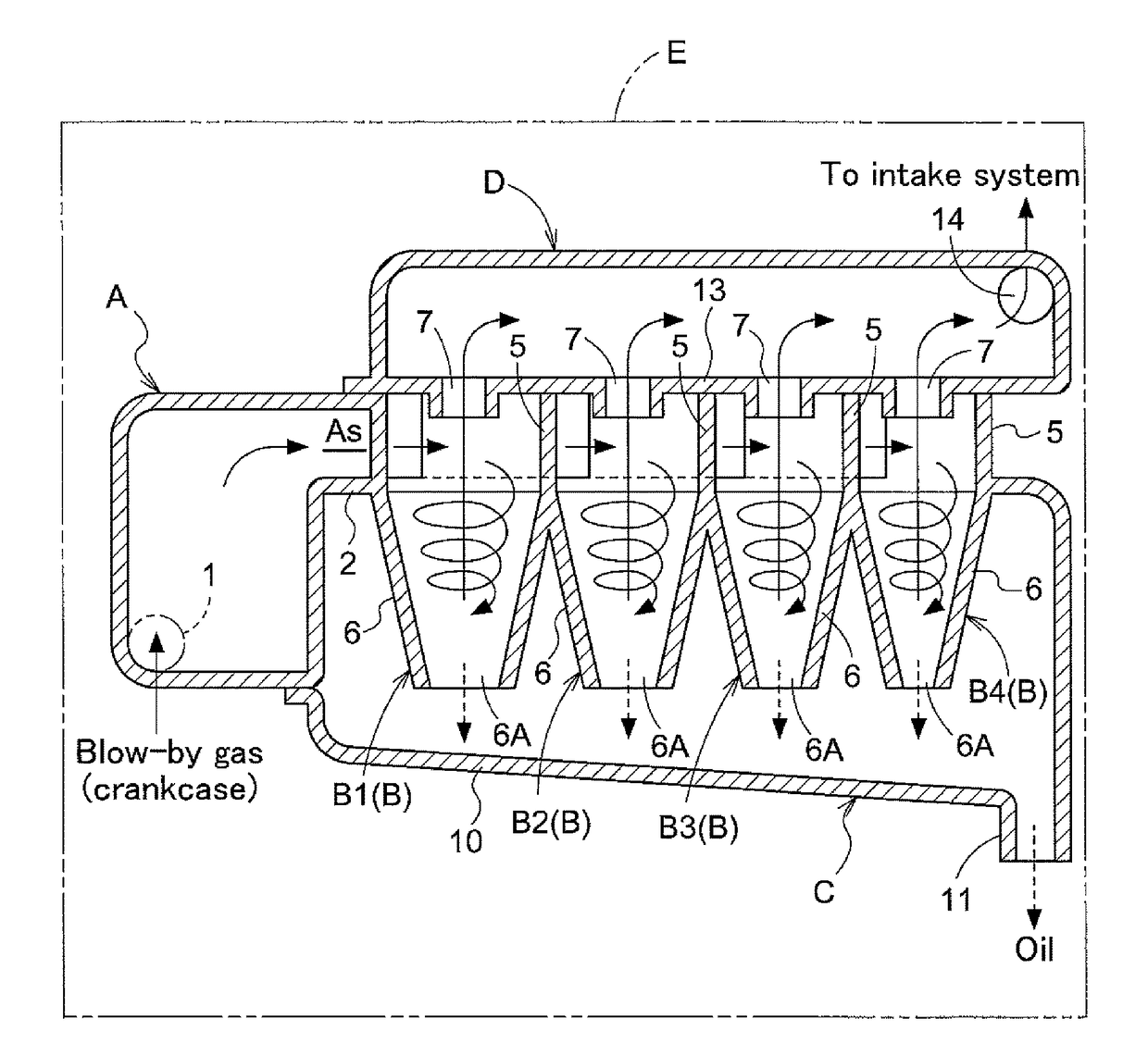
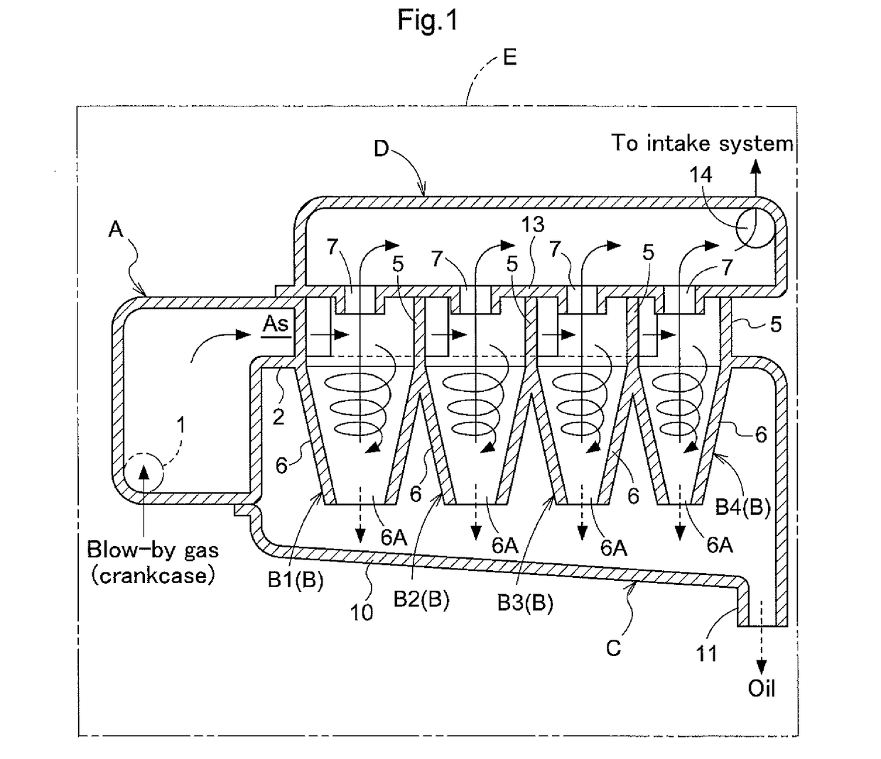
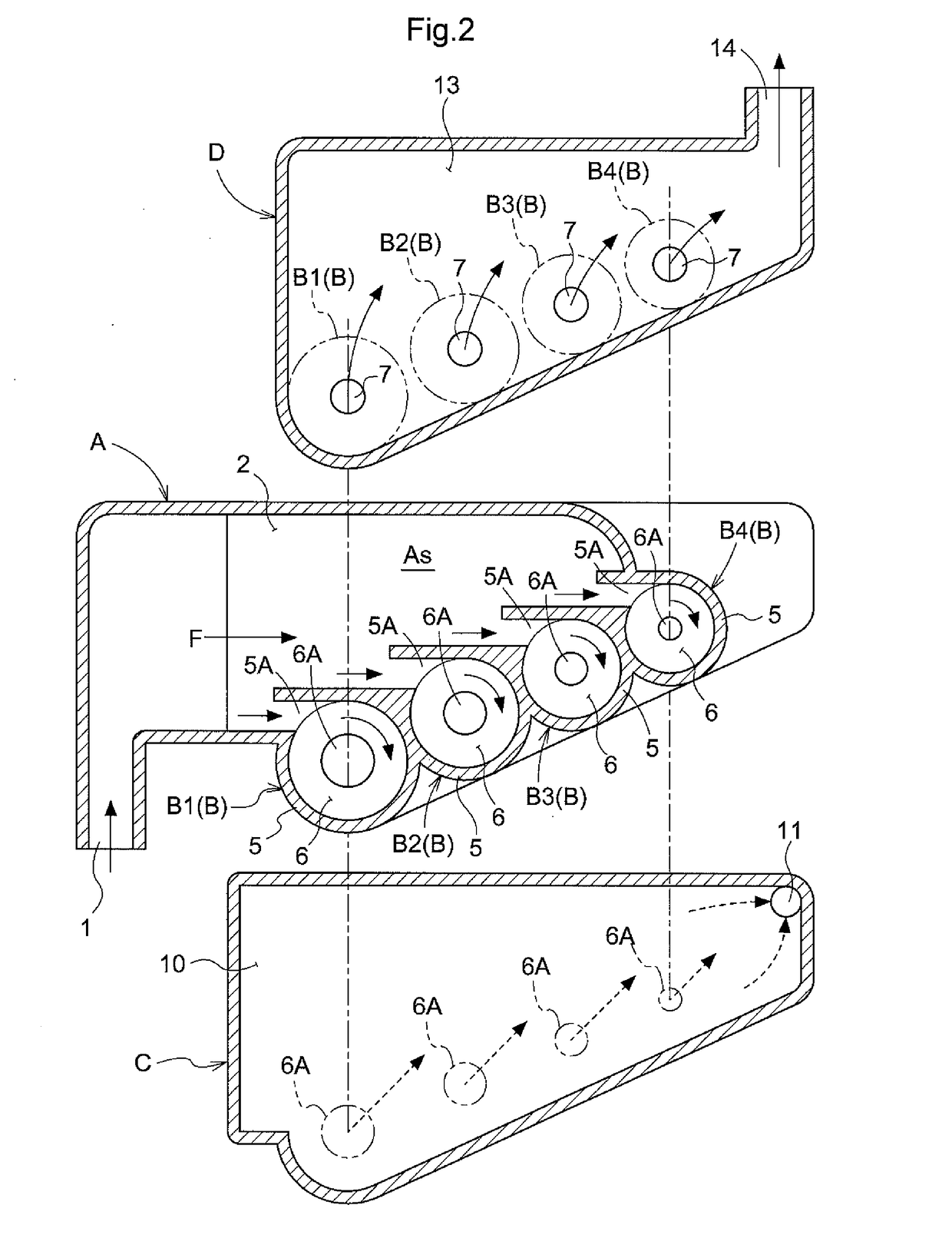
[0020]As shown in FIGS. 1 and 2, an oil separator is configured by a gas supply portion A, four cyclone-type oil separation units B that separate out oil mist contained in blow-by gas from the gas supply portion A, an oil recovery portion C that recovers the oil collected by the oil separation units B, and a gas discharge portion D that discharges the blow-by gas from which oil mist was separated by the oil separation units B.

[0021]In this oil separator, blow-by gas produced in the crankcase of an engine E, which is an internal combustion engine, passes through a passage for return to the intake system of the engine E, and the oil separator has a function in which by causing the blow-by gas to flow from the gas supply portion A to the gas discharge portion D via the four oil separation units B, oil mist contained in the blow-by gas is separated out and collected by ...


PUM


Abstract

An oil separator is provided that efficiently recovers oil mist in blow-by gas regardless of differences in particle diameter. The oil separator includes a supply space to which blow-by gas from an internal combustion engine is supplied, and multiple cyclone-type oil separation units arranged along the gas supply direction, each having a cylindrical cylinder case part to which the blow-by gas from the supply space is supplied. An inner diameter of the cylinder case part of the oil separation unit is set larger with the oil separation unit arranged more upstream in the gas supply direction.

Description

TECHNICAL FIELD[0001]The present invention relates to an oil separator that separates oil mist from blow-by gas.BACKGROUND ART[0002]In an engine, when gas mixture is introduced to a combustion chamber during running, some unburned gas mixture leaks into the crankcase through the gap between the piston and the cylinder. This leaked gas is called blow-by gas, and it is prohibited by law to discharge this blow-by gas as is into the atmosphere as exhaust gas. For this reason, blow-by gas is returned to the intake port via a PCV (Positive Crankcase Ventilation) passage, reintroduced into the combustion chamber along with new gas mixture, and burned in the combustion chamber.[0003]Blow-by gas contains lubricating oil such as engine oil in the form of an oil mist, and it is not preferable for blow-by gas containing oil mist to be returned to the intake port since oil will stick to the PCV passage and the periphery of the intake port. In view of this, an oil separator is provided inside the...

Claims


Application Information

Patent Timeline
Patent Type & Authority Patents(United States)
IPC IPC(8): F01M13/00F01M13/04F01M13/02
CPCF01M13/04F01M13/00F01M13/02F01M13/021F01M13/022F01M2013/0066F01M2013/0422F01M2013/0427F01M2013/0438
Inventor KIRA, NAOKINISHIGAKI, ATSUSHIIKEDA, JUNSATSUMABAYASHI, SHIN
Owner AISIN SEIKI KK
Learn More