

Floating actuator control system and method
a technology of actuator control and control system, which is applied in the direction of ventilation system, ignition automatic control, heating types, etc., can solve the problems of limited heating effect, large temperature swing, and inability to control 100% or 0% heating, so as to improve the control of the actuator, eliminate or substantially reduce wear, and improve the effect of actuator control
- Summary
- Abstract
- Description
- Claims
- Application Information
AI Technical Summary
Benefits of technology
Problems solved by technology
Method used
Image

Examples
Embodiment Construction
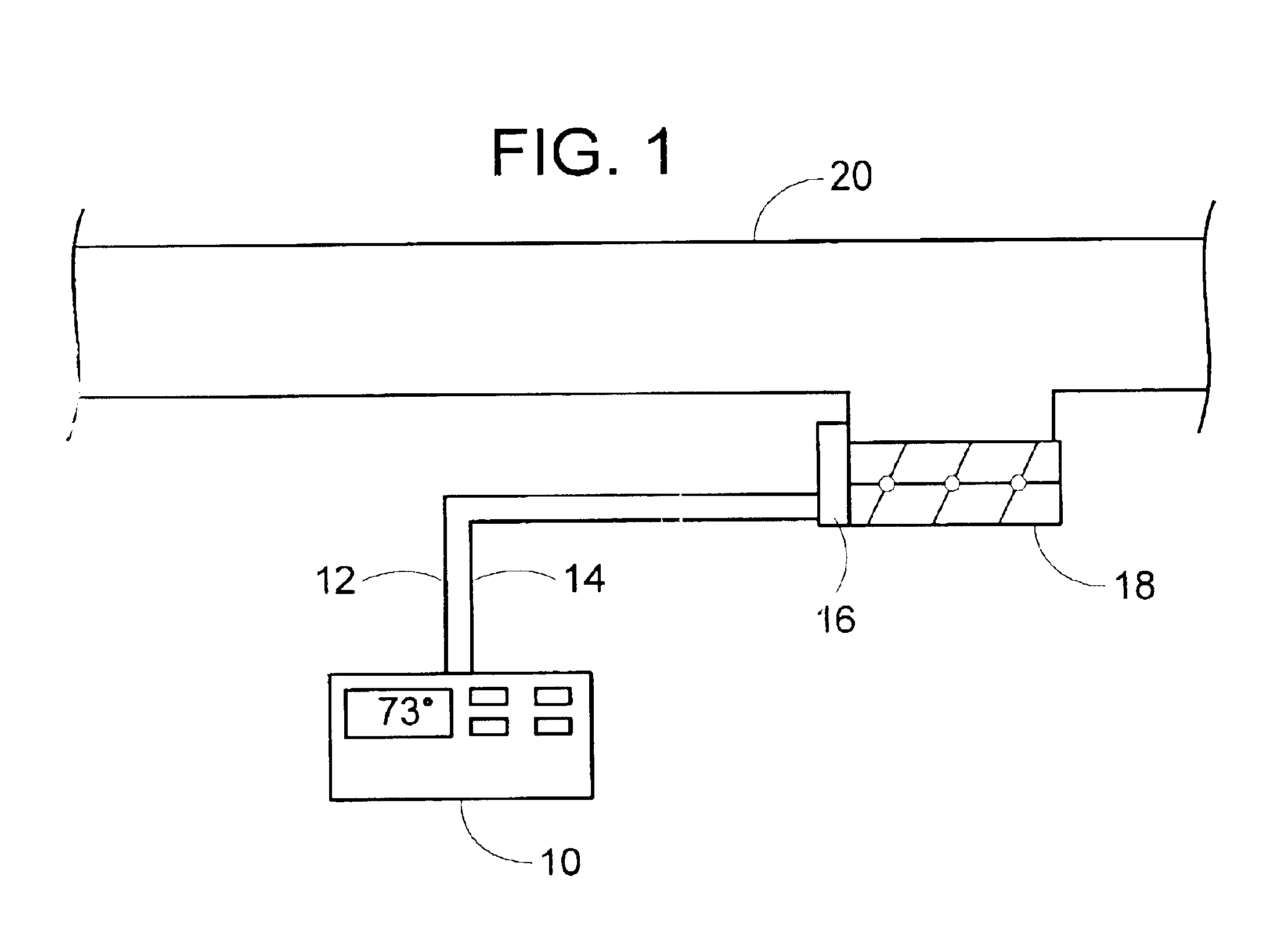
While the system and method of the present invention are applicable to various installations and system configurations, FIG. 1 illustrates a typical installation that will aid in the understanding of the operation of the system and method of the present invention. As may be seen from this simplified FIG. 1, a temperature controller 10, which may or may not include remote temperature sensors, provides the control inputs for controlling the ambient temperature within its control zone. The setting and programming of this HVAC zone temperature controller is beyond the scope of the present invention, and will not be discussed herein except to say that the user may program the desired zone temperature and the controller 10 will process the temperature sense inputs to generate the floating actuator control signals. These control signals are illustrated in simplified form by close line 12 and open line 14. As discussed above, and as will be recognized by those skilled in the art, actuation ...
PUM
 Abstract
Description
Claims
Application Information