Linear voltage controlled capacitance circuit

a capacitance circuit and voltage control technology, applied in waveguide type devices, discontinuous tuning with variable tuning elements, continuous tuning, etc., can solve the problems of limited usefulness of mos varactor elements, and achieve wide tuning voltage range, high q capacitance, and eliminate or reduce disadvantages and problems

Inactive Publication Date: 2005-02-08
NAT SEMICON CORP
View PDF4 Cites 40 Cited by
  • Summary
  • Abstract
  • Description
  • Claims
  • Application Information

AI Technical Summary

Benefits of technology

In accordance with the present invention, a linear voltage controlled capacitance circuit with a controlled gain constant is provided that substantially eliminate or reduce disadvantages and problems associated with conventional systems. In pa...

Problems solved by technology

However, the strongly non-linear capacitance-voltage (CV) transfer characteristic, co...

Method used


Image

  • Linear voltage controlled capacitance circuit
  • Linear voltage controlled capacitance circuit
  • Linear voltage controlled capacitance circuit

Examples


Embodiment Construction

FIGS. 1 through 3, discussed below, and the various embodiments used to describe the principles of the present invention in this patent document are by way of illustration only and should not be construed in any way to limit the scope of the invention. Those skilled in the art will understand that the principles of the present invention may be implemented in any suitably arranged tank circuit.

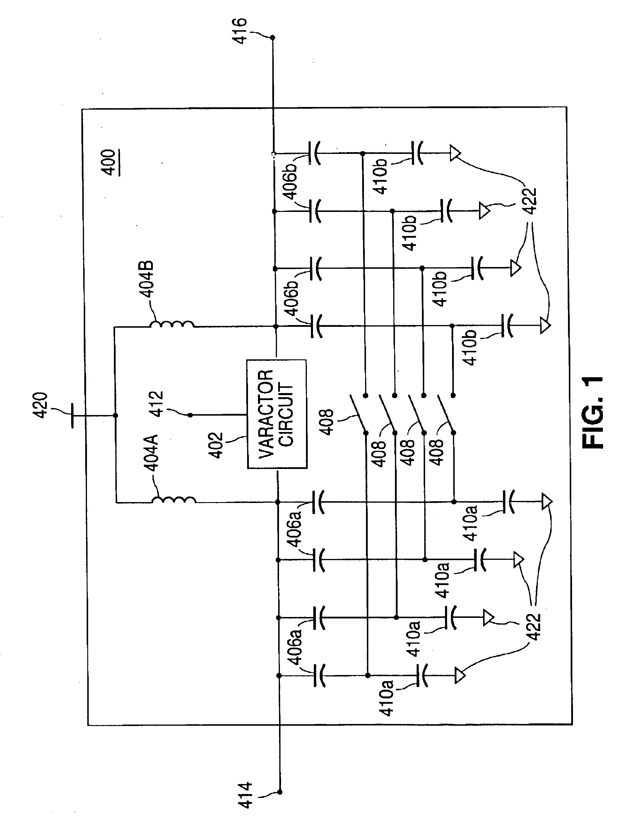
FIG. 1 is a block diagram illustrating a tank circuit 400 in accordance with one embodiment of the present invention. The tank circuit 400 may be implemented in a voltage controlled oscillator, a resonant filter, or any other suitable device. The tank circuit 400 comprises a varactor circuit 402, a plurality of inductors 404, a plurality of capacitors 406 and 410, and a plurality of switches 408.

Although the illustrated tank circuit 400 comprises eight capacitors 406 and 410 and four switches 408, it will be understood that the tank circuit 400 may comprise any suitable number of capacitors 406...


PUM


Abstract

A linear voltage controlled capacitance circuit is provided that includes a plurality of MOS varactor pairs. Each MOS varactor pair is operable to receive a first tuning voltage, a second tuning voltage, and a bias voltage unique to the MOS varactor pair. The capacitance circuit is operable to generate a positive tank node signal and a negative tank node signal based on the first and second tuning voltages and the bias voltages. A means to control voltage-to-capacitance gain is also provided to compensate for coarse tuning capacitance change.

Description

TECHNICAL FIELD OF THE INVENTIONThe present invention relates generally to resonant LC tank circuits employed in programmable tuned circuit applications and, more particularly, to a linear voltage controlled capacitance circuit with fine tuning gain compensation.BACKGROUND OF THE INVENTIONVoltage controlled capacitance elements, or varactors, are useful in oscillator circuits that are commonly used in communication devices, as well as in many other applications. Resonant tank circuits are often used for radio frequency oscillator circuits because of their high-resonance frequency of operation, low phase and amplitude noise, and low power consumption. In order to tune such a circuit, capacitance is typically controlled by an external circuit to vary the frequency of resonance. A large capacitance control variance range is often necessary to compensate for manufacturing variances of the individual components, as well as to provide a means to cover a wide tuning frequency range in many...

Claims


Application Information

Patent Timeline
IPC IPC(8): H03J3/20H01P1/10H03J3/00H03J3/18H01P1/15H03B1/00
CPCH01P1/15H03J3/20H03J3/185H03B2201/025H03J2200/38H03J2200/10
Inventor HUGHES, RODNEY ALAN
Owner NAT SEMICON CORP
Why Eureka
Try Eureka