Compact high-power reflective-cavity backed spiral antenna

a spiral antenna, reflective cavity technology, applied in the field of spiral antennas, can solve the problems of reducing the power capacity of spiral antennas,

Inactive Publication Date: 2005-02-08
EXCELIS INC
View PDF15 Cites 158 Cited by
  • Summary
  • Abstract
  • Description
  • Claims
  • Application Information

AI Technical Summary

Benefits of technology

To meet this and other needs, and in view of its purposes, the present invention provides an antenna device comprising a substrate, and a radiating element disposed on the substrate. The radiating element includes two spiral arms unfurling in

Problems solved by technology

Under these circumstances, the spiral antenna device dissipates half the signal and is primarily used in receivers, which are limited to low power.
These devices, however, are limited to

Method used


Image

  • Compact high-power reflective-cavity backed spiral antenna
  • Compact high-power reflective-cavity backed spiral antenna
  • Compact high-power reflective-cavity backed spiral antenna

Examples


Embodiment Construction

For purposes of clearer description, the invention is described in terms of transmission into free space, commonly referred to as radiation. This does not restrict the invention from performing receiving functions or simultaneous transmit / receive (T / R) functions, since the antenna is reciprocal and provides identical characteristics in both modes of operation.

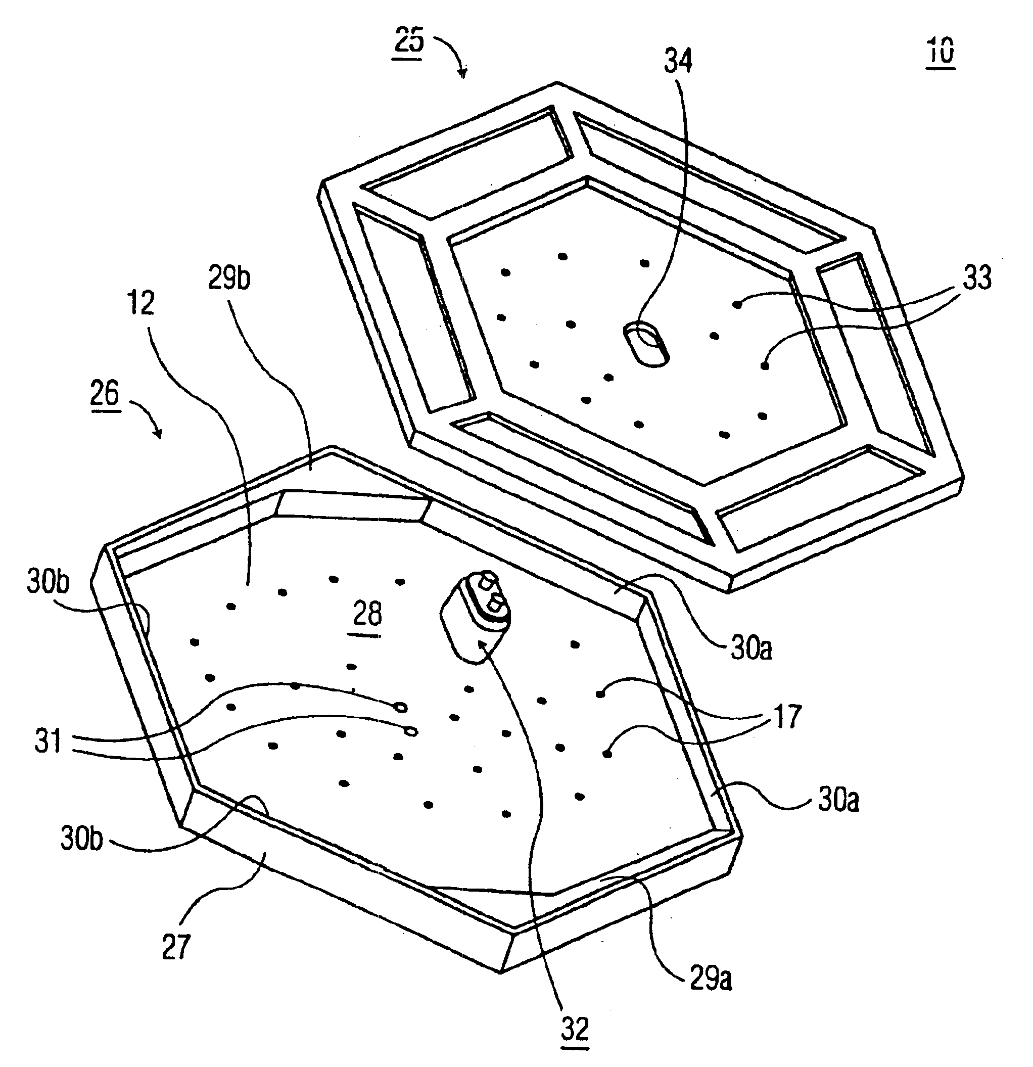
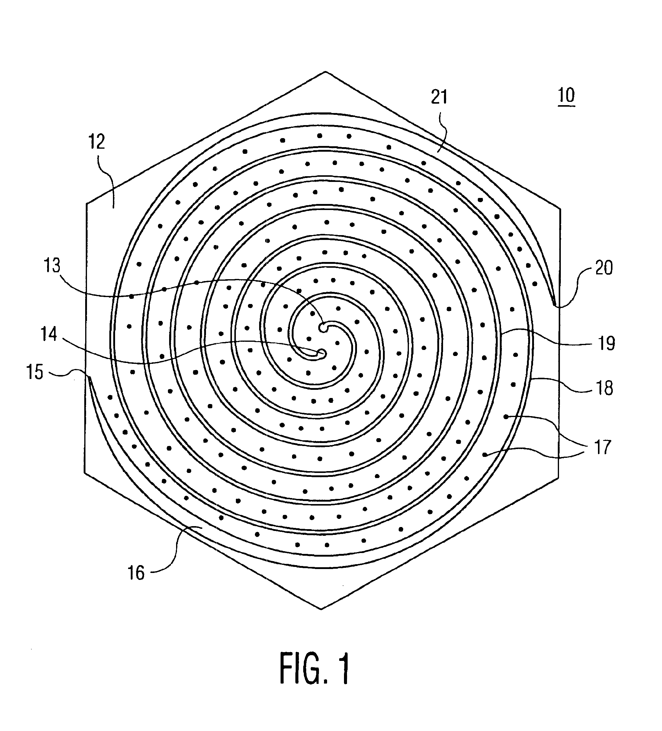
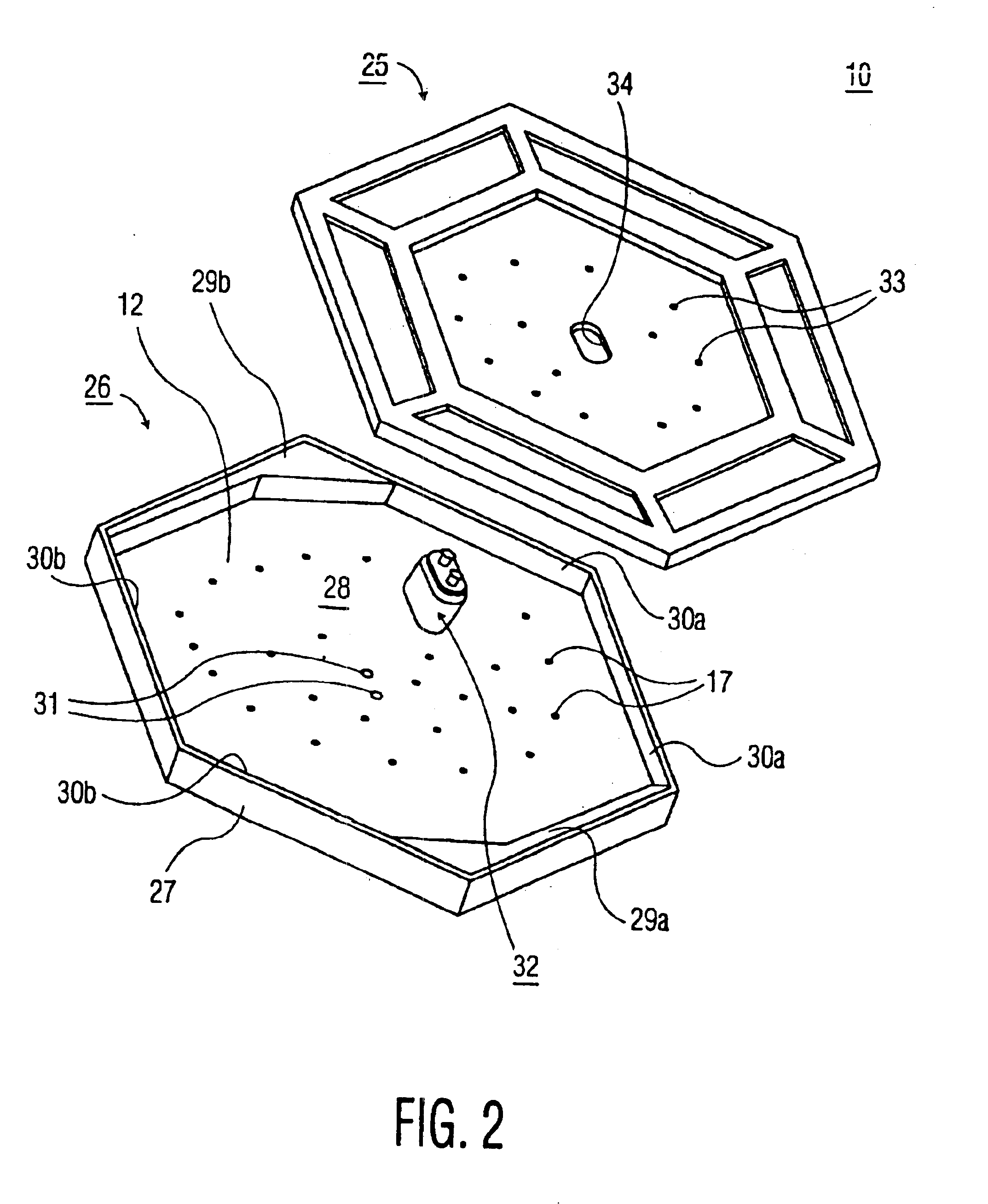
Referring now to the figures, wherein like references refer to like elements of the invention, a compact high-power reflective-cavity backed spiral antenna device is illustrated in FIGS. 1 and 2, and is generally designated as 10. As shown, antenna device 10 includes support structure 26 having substrate 12 mounted on hexagonal wall 27 at one end and cover 25 mounted on hexagonal wall 27 at another end. The spiral pattern of the antenna cannot be seen perspectively in FIG. 2 and is seen in FIG. 1. When cover 25 is seated on support structure 26, enclosed cavity 28 is formed.

Referring to FIG. 1, substrate 12 includes a radiating...


PUM


Abstract

An antenna device includes a substrate, and a radiating element disposed on the substrate. The radiating element has two spiral arms unfurling in an Archimedean progression and terminating in a logarithmic progression. The substrate is formed from a dielectric material and includes multiple perforations for providing passage of coolant through the substrate. The radiating element is disposed on a front surface of the substrate, and an enclosure is formed on a rear surface of the substrate to provide a reflective cavity for reflecting radiation to the front surface of the substrate. The enclosure includes a hexagonal perimeter formed by a wall. The antenna device may be used as an element in a planar phased array.

Description

FIELD OF THE INVENTIONThe present invention relates, in general, to antennas and, more specifically, to reflective-cavity backed spiral antennas, operating over a broad frequency range, that may be used as stand-alone radiators or as modular components of phased arrays.BACKGROUND OF THE INVENTIONSpiral antenna devices are used in a myriad of applications requiring broad frequency coverage. These devices typically include patch or microstrip antennas having Archimedean, logarithmic, equiangular, sinuous or multi-arm planar configurations, as described in U.S. Pat. No. 5,508,710, issued Apr. 16, 1996 to Wang et al. In general, antenna elements are disposed on dielectric substrates, which radiate outwardly from both sides of the substrate.A cavity is placed on one side of the substrate to trap or absorb radiation in an unwanted direction. The trapped radiation or energy must be either terminated or recombined with radiation in a desired direction, so that a resulting radiation pattern ...

Claims


Application Information

Patent Timeline
IPC IPC(8): H01Q9/04H01Q13/10H01Q9/28H01Q13/18H01Q19/10H01Q9/27
CPCH01Q9/27H01Q9/28H01Q19/10H01Q13/18H01Q9/285
Inventor MOHUCHY, WOLODYMYR
Owner EXCELIS INC
Why Eureka
Try Eureka