Collimating optical member for real world simulation

a technology of optical components and simulators, applied in the field of simulators, can solve the problems of radical changes in apparent image size, radical disparity between expected image position and actual image position, and image presented on these sorts of systems lack realistic image change responses to head movemen

Active Publication Date: 2005-02-08
OPTICAL RESOLUTIONS +1
View PDF2 Cites 260 Cited by
  • Summary
  • Abstract
  • Description
  • Claims
  • Application Information

AI Technical Summary

Problems solved by technology

Accordingly, images presented on these sorts of systems lack realistic image change responses to head movement, eye movement and the like.
Such user movement results in radical changes in apparent image size.
The problem stems from the fact that the simulated scene on a display is located a relatively finite distance from the user, perhaps 40 cm.
Accordingly, head movement of a few centimeters causes radical disparity between expected image position and actual image position.
Nevertheless, such displays, while accepted by the human brain, fail to provide the numerous visual cues such as image movement, parallax, image size and the like, that inform and then guide reactions.
Accordingly, merely providing a picture-type display is not suitable for experience-based training, such as that required by aircraft pilots, watercraft pilots, seaman and the like, fighting vehicle drivers, astronauts, drivers, and so forth, as well as gunnery, navigation and other personnel associated with vehicles and fixed installations such as bunkers, communication facilities and defensive / offensive gun emplacements.
While, in principle, refractive optics can perform this function, as a practical matter, the weight, thickness, and aberrations associated with refractive optics renders such an approach impractical.
However, reflective optics present a multitude of challenges.
If the image is presented by folding the axis by the use of a partially reflective, partially transmissive planar optic, the assembly is clumsy and the presentation of adjacent assemblies complicated or impossible.
While, in principle, one may replace the concave optic with a half-silvered concave member, holographic equivalent thereof, or the like, the direct view of the original image may destroy the usefullness of the effect.
However, in theory, every transmission through and reflection off a half-silvered optical member and certain transmissions through a polarizer involve a nominal fifty percent loss of intensity.
However, such systems suffer from the inadequacy of the cholesteric polarizer which has a relatively narrow range of reflectivity and requires the use of, for example, three layers of optics, resulting in a relatively thick assembly forming the collimating optical simulator member, and presentation of images with multiple color components which are out of register with each other.

Method used


Image

  • Collimating optical member for real world simulation
  • Collimating optical member for real world simulation

Examples


Embodiment Construction

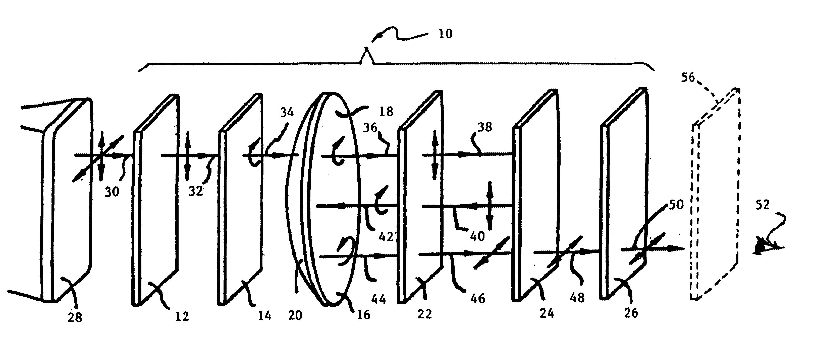
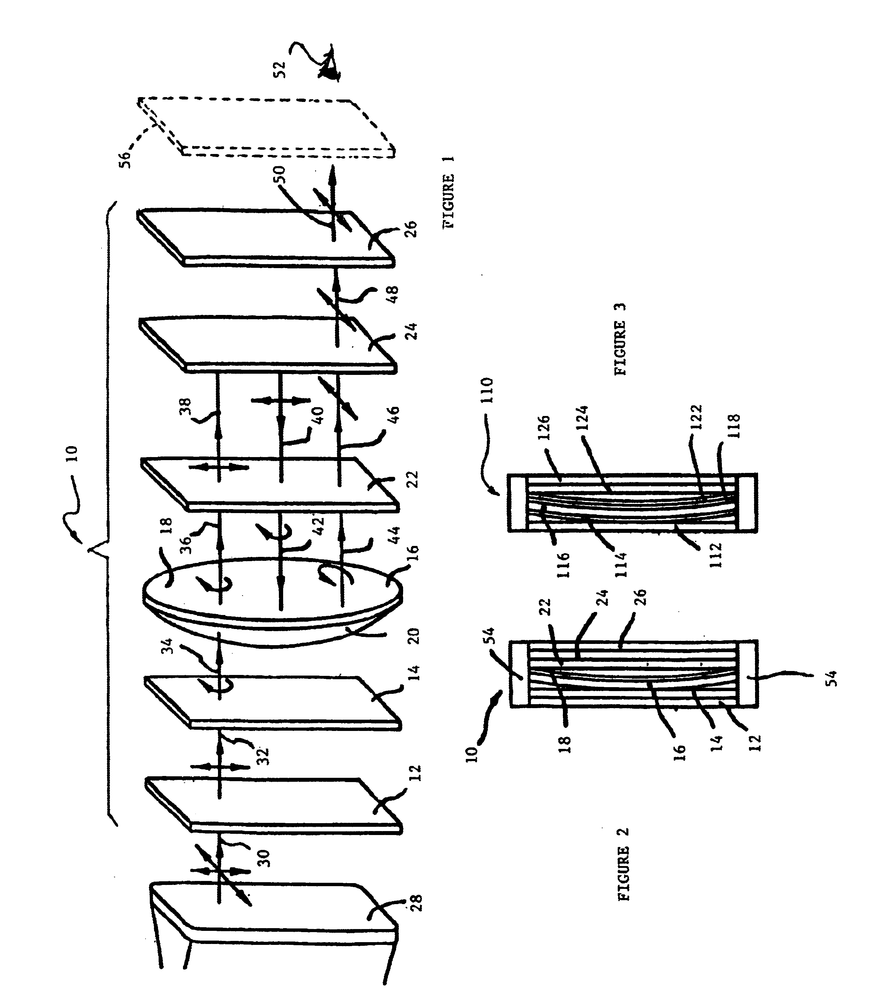
Referring to FIG. 1, in accordance with the invention, a collimator 10 comprises a polarizer 12, having a vertical polarization orientation. Polarizer 12 transmits light to a quarter wave plate 14 which outputs right circular polarized light to focusing mirror 16. Focusing concave mirror 16 is a concave mirror having a half silvered surface 18 coated on a concave glass substrate 20. Concave mirror 16 is optically coupled to a second quarter wave plate 22 which is optically coupled to both concave mirror 16 and a panchromatic reflective / transmissive polarizer 24 which is optically coupled to both quarter wave plate 22 and horizontal polarizer 26. In accordance with the invention, it is noted that the horizontal and vertical polarizers may be at different angles, provided that they are substantially at right angles to each other.

In accordance with the preferred embodiment of the invention, reflective / transmissive polarizer 24 is made using liquid crystal and photoimageable alignment m...


PUM

PropertyMeasurementUnit
distanceaaaaaaaaaa
anglesaaaaaaaaaa
angleaaaaaaaaaa

Abstract

A collimating image-forming apparatus comprising a first linear polarizer is disclosed. A first quarter-wave plate is disposed adjacent the first polarizer and has its fast and slow axes at substantially 45° to the plane of polarization of the first polarizer. The apparatus further comprises a beam-splitting curved mirror having a convex surface adjacent the first polarizer and facing towards the first quarter-wave plate, a second quarter-wave plate adjacent the concave side of the curved mirror, the second quarter-wave plate having its having its fast and slow axes oriented with respect to the corresponding axes of the first quarter-wave plate at angles substantially equal to a first integral multiple of 90°, and a reflective-transmissive polarizing member adjacent the second quarter-wave plate. A second linear polarizer is adjacent the reflective-transmissive polarizing member, the second linear polarizer having its plane of polarization oriented with respect to the plane of polarization of the first linear polarizer at an angle substantially equal to a second integral multiple of 90°, both of the multiples being even or both being odd.

Description

TECHNICAL FIELDThe present invention relates to collimating displays for simulators for presenting objects that appear to be at a great distance.STATEMENT REGARDING FEDERALLY SPONSORED RESEARCH OR DEVELOPMENTNot Applicable.CROSS-REFERENCE TO RELATED APPLICATIONSNot Applicable.BACKGROUNDSimulation of the real world is implemented in a wide variety of applications ranging from vehicle training simulators to video games. The simplest simulators are those used, for example, in video games. Generally, such simulators utilize a video display presented on a cathode ray tube monitor or a liquid crystal display. Such displays are meant to simulate the appearance of an outside world view seen through a window. The analog of the real world window in a display is, for example, the face of the liquid crystal display. The display has dimensionality, motion characteristics and perspective characteristics similar to those of a video image produced by a video camera. Accordingly, images presented on...

Claims


Application Information

Patent Timeline
Patent Type & Authority Patents(United States)
IPC IPC(8): G02B27/28G02B30/25
CPCG02B5/3016G02B27/0172G02B27/286
Inventor RUHLE, FRANKWEISSMAN, PAUL
Owner OPTICAL RESOLUTIONS
Why Eureka
Try Eureka