
Zoom lens system

Inactive Publication Date: 2005-02-08
ASAHI KOGAKU KOGYO KK
View PDF14 Cites 13 Cited by
  • Summary
  • Abstract
  • Description
  • Claims
  • Application Information

AI Technical Summary

Benefits of technology

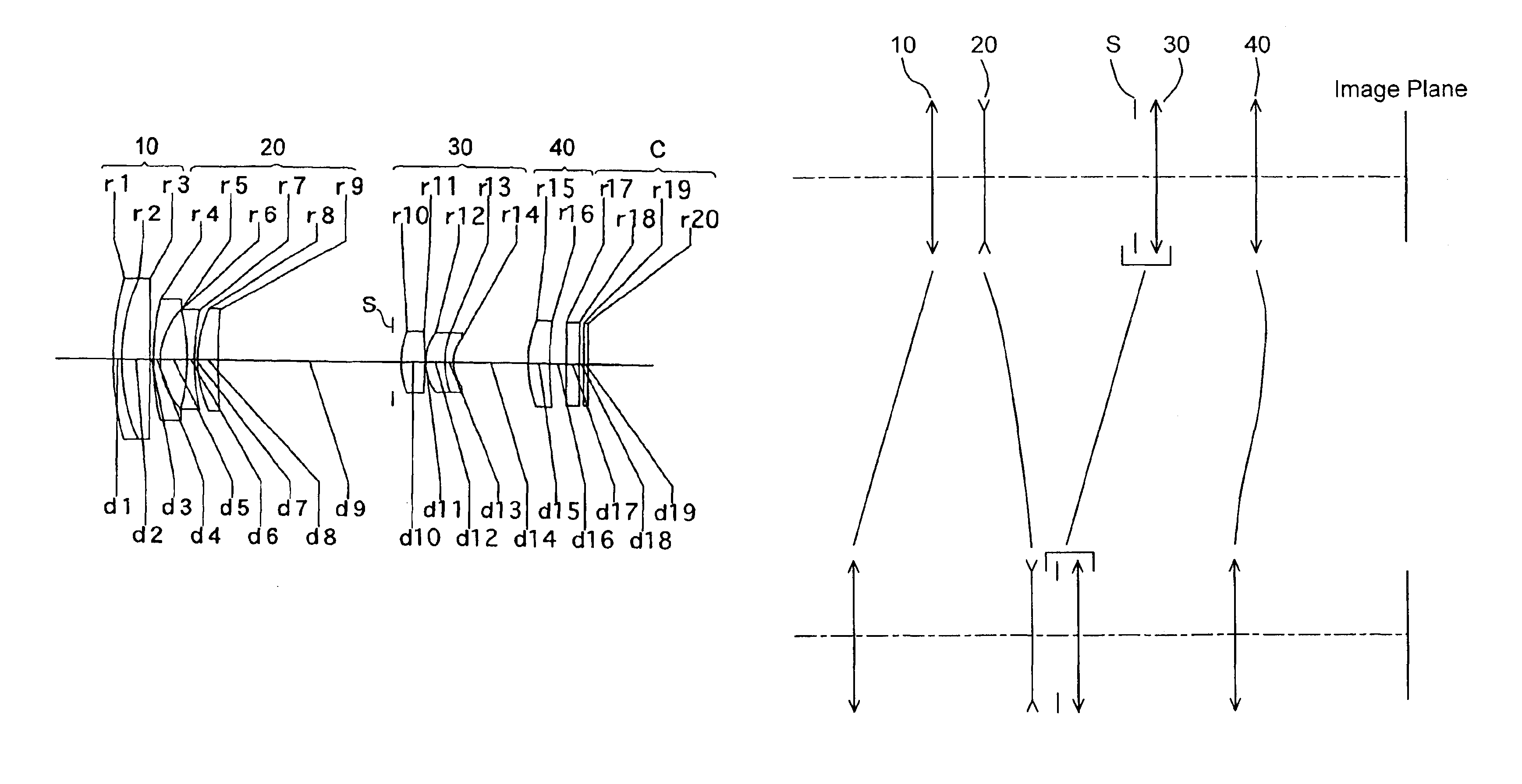
Upon zooming from the short focal length extremity to the long focal length extremity, all the lens group are arranged to be movable in a manner that the distance between the positive first lens group and the negative second lens group increases, the distance between the negative second lens group and the positive third lens group decreases, the distance between the positive third lens group and the positive fourth lens group increases, and the distance between the positive first lens group and the positive third lens group does not change.
Due to the integral movement of the positive first lens group and the positive third lens group, the structure of the lens barrel can be made simpler, and the diameter of the lens group can be made smaller. Furthermore, due to such simplification, precision on decentration can be enhanced, and stabilization on imaging performance at a production process can be attained. Accordingly, miniaturization of a compact camera employing a multi retractable lens barrels can be attained. Moreover, the positive fourth lens group is arranged to move in the U-turn path, and to satisfy condition (1); thereby, peripheral illumination which tends to decrease from the short focal length extremity toward an intermediate focal length can be secured.

Problems solved by technology

However, in such a zoom lens system (negative-lead type lens system), it is difficult to achieve a zoom ratio of 4 or more.
A zoom ratio of about 6 is achieved in U.S. Pat. No. 5,100,223 and a zoom ratio of about 10 is achieved in U.S. Pat. No. 5,570,233; however, in both publications, the diameter of the front lens group is large, and miniaturization of the camera is not sufficiently attained.
Furthermore, in U.S. Pat. No. 5,100,223, the half angle-of-view at the short focal length extremity is about 25°, which means that a wide angle-of-view, i.e., the shorter focal length at the short focal length extremity, is not sufficiently achieved.
U.S. Pat. No. 5,570,233 achieved a wide angle of view; however, the front lens diameter is large, and employs a large number of lens elements, which is not suitable for a retractable zoom lens system for a camera.
Generally, if the number of lens groups is reduced, the mechanical construction therefor can be simplified; however, it is difficult, on the other hand, to achieve a higher zoom ratio.
However, if the number of lens elements is reduced in order to miniaturize the zoom lens system, and if the thickness of the lens group is reduced, the correcting of aberrations becomes increasingly difficult.

Method used


Image

  • Zoom lens system
  • Zoom lens system
  • Zoom lens system

Examples


embodiment 2

[Embodiment 2]

FIG. 6 is a lens arrangement of a zoom lens system according to the second embodiment of the present invention. FIGS. 7A through 7D show aberrations occurred in the lens arrangement shown in FIG. 6 at the short focal length extremity. FIGS. 8A through 8D show aberrations occurred in the lens arrangement shown in FIG. 6 at a first intermediate focal length (on the side of the short focal length). FIGS. 9A through 9D show aberrations occurred in the lens arrangement shown in FIG. 6 at a second intermediate focal length (on the side of the long focal length). FIGS. 10A through 10D show aberrations occurred in the lens arrangement shown in FIG. 6 at the long focal length extremity. Table 2 shows the numerical data of the second embodiment.

The basic lens arrangement of the second embodiment is the same as that of the first embodiment. The diaphragm S is provided 0.97 in front (on the object side) of surface No. 10 (the positive third lens group 30).

The fourth lens group 40 ...

embodiment 3

[Embodiment 3]

FIG. 11 is a lens arrangement of a zoom lens system according to the third embodiment of the present invention. FIGS. 12A through 12D show aberrations occurred in the lens arrangement shown in FIG. 11 at the short focal length extremity. FIGS. 13A through 13D show aberrations occurred in the lens arrangement shown in FIG. 11 at a first intermediate focal length (on the side of the short focal length). FIGS. 14A through 14D show aberrations occurred in the lens arrangement shown in FIG. 11 at a second intermediate focal length (on the side of the long focal length). FIGS. 15A through 15D show aberrations occurred in the lens arrangement shown in FIG. 11 at the long focal length extremity. Table 3 shows the numerical data of the third embodiment.

The basic lens arrangement of the third embodiment is the same as that of the first embodiment. The diaphragm S is provided 0.97 in front (on the object side) of surface No. 10 (the third lens group 30).

The fourth lens group 40 c...

embodiment 4

[Embodiment 4]

FIG. 16 is a lens arrangement of a zoom lens system according to the fourth embodiment of the present invention.

FIGS. 17A through 17D show aberrations occurred in the lens arrangement shown in FIG. 16 at the short focal length extremity. FIGS. 18A through 18D show aberrations occurred in the lens arrangement shown in FIG. 16 at a first intermediate focal length (on the side of the short focal length). FIGS. 19A through 19D show aberrations occurred in the lens arrangement shown in FIG. 16 at a second intermediate focal length (on the side of the long focal length). FIGS. 20A through 20D show aberrations occurred in the lens arrangement shown in FIG. 16 at the long focal length extremity. Table 4 shows the numerical data of the fourth embodiment.

The basic lens arrangement of the fourth embodiment is the same as that of the first embodiment. The diaphragm S is provided 0.97 in front (on the object side) of surface No. 10 (the third lens group 30).

The fourth lens group 40...


PUM


Abstract

A zoom lens system includes a movable-positive first lens group, a movable-negative second lens group, a movable-positive third lens group, and a movable-positive fourth lens group. Upon zooming from the short to the long focal length extremities, all the lens groups are arranged to move in a manner that the distance between the first lens group and the second lens group increases, the distance between the second lens group and the third lens group decreases, the distance between the third lens group and the fourth lens group increases, and the distance between the first lens group and the third lens group does not change. Upon zooming from the short to the long focal length extremities, the fourth lens group first moves toward the image and thereafter moves toward the object in a U-turn path.

Description

BACKGROUND OF THE INVENTION1. Field of the InventionThe present invention relates to a zoom lens system, which is to be used mainly in an electronic still camera (digital camera), having a zoom ratio (magnification ratio) exceeding 4 and including a wide angle range.2. Description of the Prior ArtIn recent years, in order to meet the increased need for further miniaturization and higher precision / density of cameras, and higher density of the pixels in CCD image devices are being achieved. Accordingly, a photographing lens system for a digital camera is required to have high resolution. Furthermore, a long back focal distance is also required in order to accommodate a filter group. In an optical system for a color CCD, in order to prevent shading and color shift, good telecentricity, in which the light exits from the final lens surface of the photographing lens system is made incident on the imaging surface at an angle as close to a right angle (90°) as possible, is required.As a min...

Claims


Application Information

Patent Timeline
IPC IPC(8): G02B15/163G02B15/173
CPCG02B15/173G02B15/144113
Inventor EGUCHI, MASARU
Owner ASAHI KOGAKU KOGYO KK
Learn More