Anti-islanding device and method for grid connected inverters using random noise injection

a technology of random noise injection and inverter, which is applied in the field of electric power, can solve the problems of affecting affecting the quality of the electricity supplied to the customer, and damage to the equipment of the customer, so as to improve the harmonic content and direct current offset of the inverter current.

Inactive Publication Date: 2005-02-08
RHOMBUS ENERGY SOLUTIONS
View PDF11 Cites 49 Cited by
  • Summary
  • Abstract
  • Description
  • Claims
  • Application Information

AI Technical Summary

Benefits of technology

In one aspect, an anti-islanding device and method for inverters connected to a utility grid utilizing random noise injection eliminates a need for correcting the phase angle

Problems solved by technology

Such a condition is known as islanding, which constitutes a significant issue having substantial safety and performance implications.
For example, islanding results in a degradation of the quality of electricity supplied to the customer during the islanding period due to a lack of utility control.
Uncontrolled frequency and voltage excursion can damage customer equipment.
Further, if the grid disconnection is the result of a transient fault in the system, interrupting devices will try to re-close the grid connection after a few cycles (typically 12 to 15 cycles).
Re-closing can potentially damage the inverter since the voltages in the island are not necessarily synchronized with the grid.
When the grid is reconnected, it can have a different phase angle with respect to the islanded voltage, which can cause a large over-current that can damage the inverter already in the system and islanded with the load.
These requirements present a challenge to the industry.
These methods have serious drawbacks.
Periodically injecting a signal can interfere with the grid or the load.
In some instances, the injected signals can cancel each other, rendering the technique useless when multiple inverters are connected together.
This method is very sensitive to the gain selected for the positive feedback.
Too small of a gain can make the system ineffective, resulting in the failure to detect the islanding within the required time frame, while too large of a gain can potentially drive the system unstable.
Furthermore, if the load matches very closely with the inverter output, the change in frequency or the voltage may not be detectable.
If the grid is connected, the grid clamps the voltage and wil

Method used


Image

  • Anti-islanding device and method for grid connected inverters using random noise injection
  • Anti-islanding device and method for grid connected inverters using random noise injection
  • Anti-islanding device and method for grid connected inverters using random noise injection

Examples


Embodiment Construction

In the following description, certain specific details are set forth in order to provide a through understanding of various embodiments of the invention. However, one skilled in the art will understand that the invention may be practiced without these details. In other instances, well-known structures associated with electrical circuits and circuit elements have not been shown or described in detail to avoid unnecessarily obscuring descriptions of the embodiments of the invention.

Unless the context requires otherwise, throughout the specification and claims which follow, the word “comprise” and variations thereof, such as “comprises” and “comprising,” are to be construed in an open, inclusive sense, that is as “including, but not limited to.”

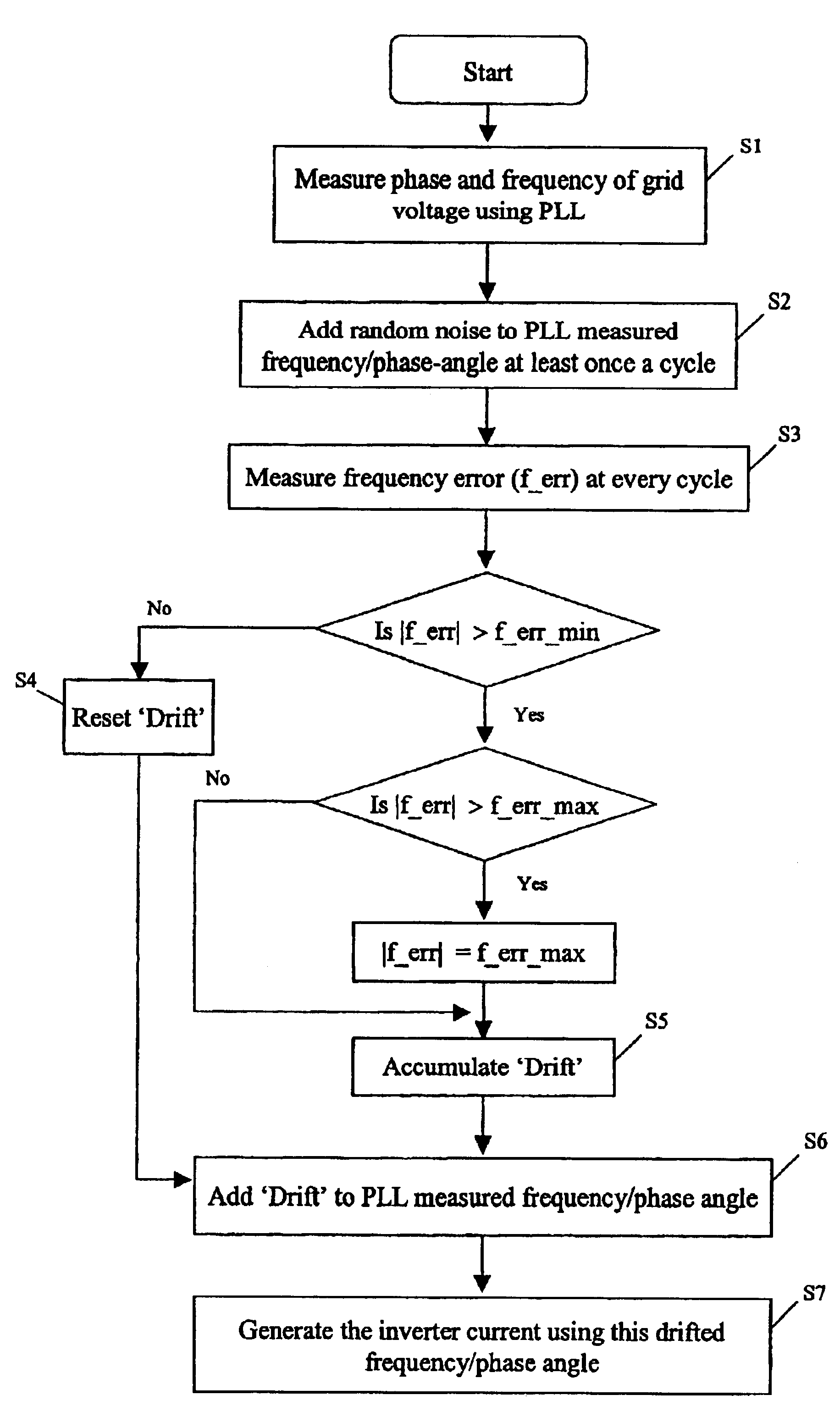
The below teachings make use, for example, of frequency drift but with an injection of white noise. The white noise acts as an injected signal, but since it is white noise it does not create any “color” or harmonics in the system. Further, its a...


PUM


Abstract

A device and method for detecting islanding of a grid connected inverter makes use of an injected white noise as a perturbing force on the output voltage of the inverter. The white noise is injected at least once in every cycle and can be generated at different rates in implementation. On loss of the grid, a frequency drift of the output voltage is detected and a positive feedback is activated that accelerates the drift.

Description

BACKGROUND OF INVENTION1. Field of the InventionThe present invention relates generally to the field of electric power, and more particularly to an anti-islanding device and method for inverters connected to a utility grid.2. Description of the Related ArtFIG. 1 shows an example of a connection of an inverter 10 to a utility grid 12 and a local load 13. When circuit breaker CB1 is closed and circuit breaker CB2 is open, the load 13 is completely supplied by the inverter 10. When circuit breaker CB2 is closed and circuit breaker CB1 is open, the load 13 is supplied by the grid 12. When both circuit breakers are closed, the load 13 can get power from both the inverter 10 and the grid 12 depending upon the power output of the inverter 10 and the capacity of the load 13 itself. If the output power of the inverter 10 is greater than the capacity of the load 13, the remaining power from the inverter 10 flows to the grid 12 and vice versa. When the power of the inverter 10 matches exactly ...

Claims


Application Information

Patent Timeline
IPC IPC(8): H02J3/38
CPCH02J3/38H02J2003/388H02J3/388
Inventor TULADHAR, ANIL
Owner RHOMBUS ENERGY SOLUTIONS
Why Eureka
Try Eureka