Rail connector and method

a technology of rail connectors and connectors, applied in the direction of cartridge extractors, butts, weapons, etc., can solve problems such as alignment problems, and achieve the effect of maintaining the alignment of various accessories mounted on the weapon over time and stable alignment over tim

Inactive Publication Date: 2005-02-15
T D I ARMS SYST
View PDF18 Cites 134 Cited by
  • Summary
  • Abstract
  • Description
  • Claims
  • Application Information

AI Technical Summary

Benefits of technology

The present invention provides a rail connector for a firearm which provides stable alignment over time, during firing of the weapon or even if the weapon receives a shock, thereby substantially maintaining the alignment of various accessories mounted on the weapon over time. According to one embodiment of the invention, six separate rails are provided on the mount.
There is thus provided, is accordance with the present invention, a connector for mounting on a firearm having a front sight, the connector including at least two accessory rails, and a fastening member for securely fastening the connector directly to the front sight of the firearm, the fastening member being coupled to the rails.

Problems solved by technology

These generally are attached at the rear of the rifle only, in order to attempt to provide more stability over times However, these rails, also, suffer from alignment problems due to the shock created by the gases during firing.

Method used


Image

  • Rail connector and method
  • Rail connector and method
  • Rail connector and method

Examples


Embodiment Construction

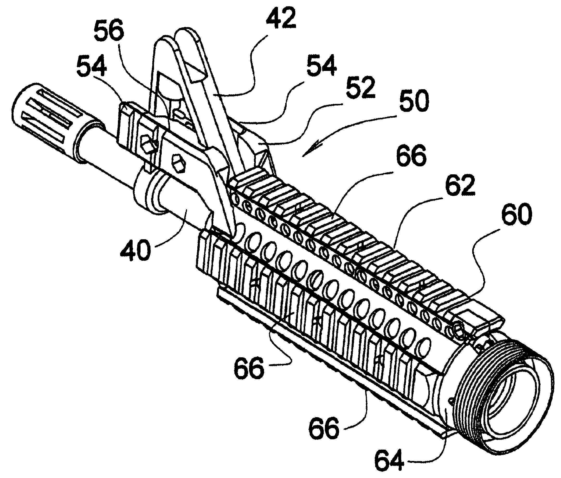
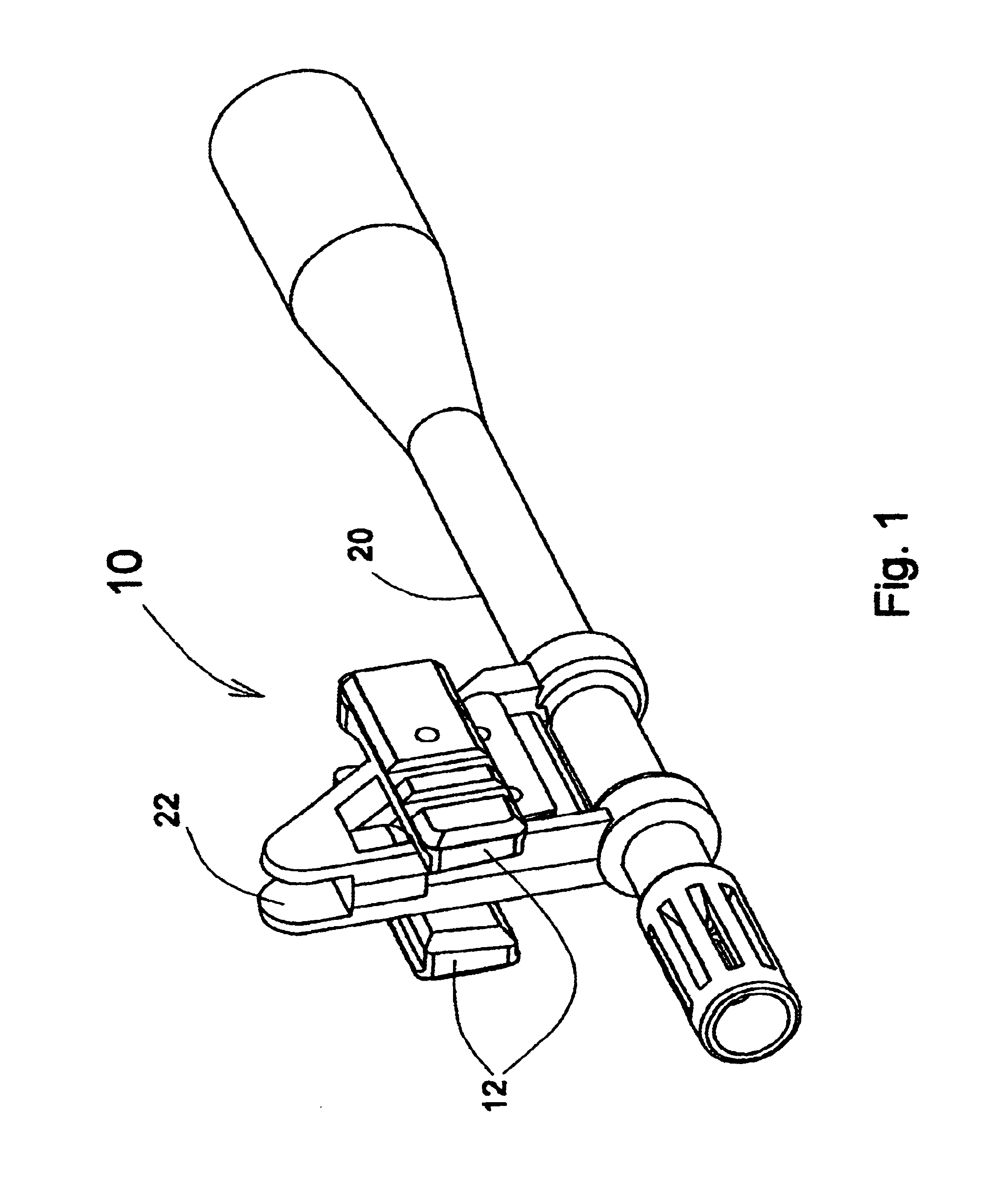
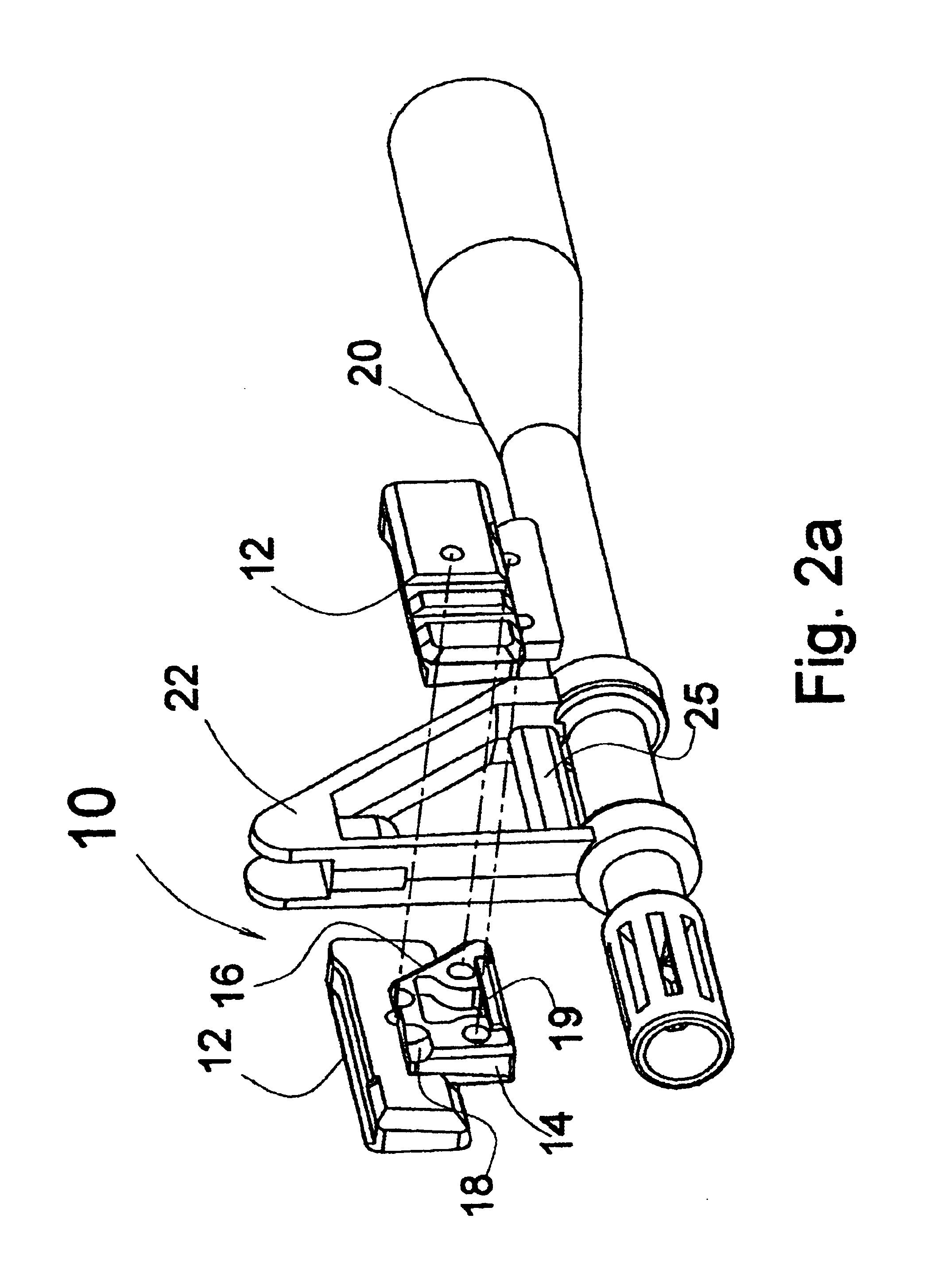
The present invention relates to connectors for mounting a plurality of rails, such as Picatinny rails according to MIL-STD-1913, or other mounting rails, on a rifle or other firearm, in a secure fashion which substantially maintains alignment of accessories mounted thereon over time. This is accomplished by affixing the connector directly to the front sight of the weapon. The invention is particularly suitable for use on the P-90 sub-machine gun of FN Herstal, SA, Herstal, Belgium, the Galil of Israel Military Industries, of Ramat Hasharon, Israel, and the family of AR15 platform based weapons (e.g., M-16, AR15, A4), manufactured and sold by Colt Defense LLC, Connecticut, USA, and AK-47 (Automat Kalashnikova, Model 1947).

It is a particular feature of the invention that the connector is mounted on the front sight as it is, without requiring removal, dismantling, or otherwise changing the sight or any other armor work. Thus, a soldier can mount the connector by himself, without requi...


PUM


Abstract

A rail connector and method for mounting on a firearm having a front sight, the connector including at least two mounting rails, and a fastening member for securely fastening the connector directly to the front sight of the firearm, the fastening member being coupled to the mounting rails.

Description

FIELD OF THE INVENTIONThe present invention relates to a rail connector for a firearm in general and, in particular, to a connector for mounting at least two rails on a rifle.BACKGROUND OF THE INVENTIONIn recent years, the increasing complexity of combat has generated a need for weapons with increased accuracy and which are capable of supporting various accessories, such as flashlights, infrared and night vision scopes, laser spotters, and so forth. Consequently, a wide variety of mounts for rifles and other hand weapons have been developed which permit the mounting of lights, scopes and the like on the weapon, often along the barrel. Such mounts are generally referred to as Modular Weapon Systems, and replace the factory handguards of the host weapon systems.These modular weapon systems generally include Picatinny or other rails or tracks, often using MIL-STD-1913 for standardization of the mounting systems, and are affixed to the barrel or stock of the rifle for mounting accessori...

Claims


Application Information

Patent Timeline
Patent Type & Authority Patents(United States)
IPC IPC(8): F41G1/34F41G1/387F41G1/35F41G1/00
CPCF41G1/34F41G11/003F41G1/35
Inventor OZ, DAVID
Owner T D I ARMS SYST
Why Eureka
Try Eureka