Fluidic device with integrated capacitive micromachined ultrasonic transducers

a micromachined ultrasonic transducer and micromachined technology, which is applied in the direction of instruments, heat measurement, specific gravity measurement, etc., can solve the problems of piezoelectric materials that cannot be easily integrated, devices are bulky, and cannot meet the other processing steps required for fluidic chips,

Inactive Publication Date: 2005-02-15
THE BOARD OF TRUSTEES OF THE LELAND STANFORD JUNIOR UNIV
View PDF11 Cites 125 Cited by
  • Summary
  • Abstract
  • Description
  • Claims
  • Application Information

AI Technical Summary

Problems solved by technology

Most of these devices are bulky, and they cannot be easily integrated to microfluidic systems for several reasons.
With a few exceptions, piezoelectric materials are not compatible with other processing steps required for the fluidic chips.
In addition, piezoelectric transducers for bulk wave excitation cannot be scaled down easily so as to fit in microfluidic channels without degrading their performance.

Method used


Image

  • Fluidic device with integrated capacitive micromachined ultrasonic transducers
  • Fluidic device with integrated capacitive micromachined ultrasonic transducers
  • Fluidic device with integrated capacitive micromachined ultrasonic transducers

Examples


Embodiment Construction

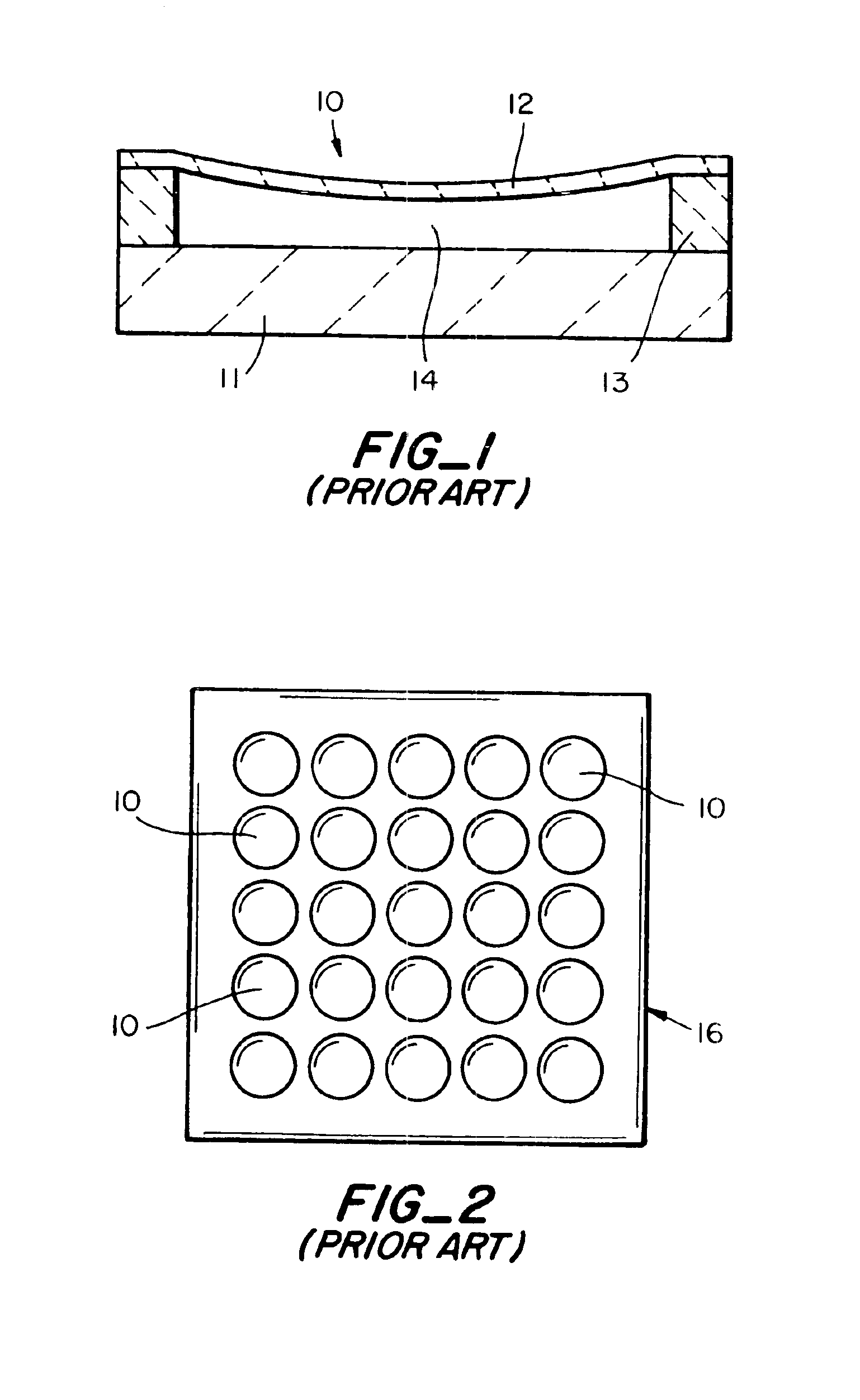
A cMUT cell is fabricated to form a structure similar to that of FIG. 1. The cell includes a substrate 11, such as silicon, and a membrane 12 such as silicon nitride supported by amorphous silicon 13. Amorphous silicon is used as a sacrificial layer that is partially removed by wet etching to form an evacuated cavity 14. A number of cells 10 are fabricated on a silicon substrate to form a transducer 16, FIG. 2. A detailed description of the methods for fabrication and operation of cMUTs is found in U.S. Pat. Nos. 5,619,476, 5,870,351 and 5,894,452, incorporated herein in their entirety. In the illustrated embodiment, the gap thickness is determined by the amorphous silicon and can be quite small, which results in improved sensitivity because in receive, one measures the change in capacity due to the motion of the membrane. Each cell is made of a vacuum-sealed, fully supported membrane with a diameter of 5-200 μm. For example, a 100 μm square transducer with individual cells 20 μm in...


PUM

PropertyMeasurementUnit
frequencyaaaaaaaaaa
diameteraaaaaaaaaa
diameteraaaaaaaaaa

Abstract

The present invention provides fluidic devices and systems which have micromachined ultrasonic transducers integrated into microchannels. The ultrasonic transducers generate and receive ultrasonic waves. The transducers can be disposed and operated to measure fluid characteristics such as pressure, density, viscosity, flow rate and can also be used to mix and pump fluids.

Description

BRIEF DESCRIPTION OF THE INVENTIONThis invention relates to a fluidic device with integrated capacitive micromachined ultrasonic transducers (cMUTs), and more particularly to a fluidic device having microchannels with cMUTs fabricated in the walls of the channels.BACKGROUND OF THE INVENTIONThe large investments in the microelectronics industry converted integrated circuits laboratories into machine shops where miniature electromechanical systems are designed and built. Electromechanical as well as electro-optical systems have been miniaturized and used in many different applications. In the same fashion, miniaturization is presently applied in the field of microfluidics. Microfluidics technology provides the advantage of being able to perform chemical and biochemical reactions and / or separations with high throughput low volumes. Microfluidic systems employ microchannels in which chemical and biochemical materials are transported, mixed, separated and detected. The object is to take ...

Claims


Application Information

Patent Timeline
Patent Type & Authority Patents(United States)
IPC IPC(8): G01N29/02G01F1/66G01N29/22
CPCB01F11/0258G01F1/662G01F1/667G01N29/022G01N29/222G01N29/223B01F13/0059G01N2291/0427G01N2291/011G01N2291/014G01N2291/017G01N2291/018G01N2291/02818G01N2291/02836G01N2291/02872G01N2291/0426B01F31/85B01F33/30
Inventor KHURI-YAKUB, BUTRUS T.DEGERTEKIN, F. LEVENT
Owner THE BOARD OF TRUSTEES OF THE LELAND STANFORD JUNIOR UNIV
Why Eureka
Try Eureka