Signal Control in Micromachined Ultrasonic Transducer

a micro-machined ultrasonic transducer and signal control technology, applied in the field of capacitive micro-machined ultrasonic transducers, can solve the problems of high-frequency harmonic distortion in the signal, difficult to use cmut to do tissue harmonic imaging (thi), and high cost, so as to achieve optimal performance and increase the level of output pressure signals.

Active Publication Date: 2007-10-04
KOLO MEDICAL (SUZHOU) CO LTD
View PDF12 Cites 39 Cited by
  • Summary
  • Abstract
  • Description
  • Claims
  • Application Information

AI Technical Summary

Benefits of technology

[0020]In one embodiment, an absolute-value signal |Vtx(t)| is used as the transmission AC signal to increase the level of the output pressure signal, where Vtx(t) is any suitable signal for the second-order frequency method described herein. The method may include a voltage level shift to shift the voltage of the absolute-value signal |Vtx(t)| and then amplify the shifted absolute-value signal to a desired amplitude (e.g., the maximum amplitude allowed by the power supply of the system). The amplified absolute-value signal is then applied with a proper DC bias on the cMUT to achieve optimal performance.

Problems solved by technology

This process is fraught with difficulties and high expenses, not to mention the large input impedance mismatch problem presented by such elements to transmit / receiving electronics.
One problem cMUT operation often has is the high-frequency harmonic distortion in the signal.
Because a large Vp-p is generally needed to generate a large enough output pressure, the existing actuation methods usually have a significant second harmonic that may distort the output pressure.
In this case, the second harmonic is comparable to the output pressure signal at the fundamental operating frequency ω. This type of distortion may make it difficult to use cMUT to do applications such as Tissue Harmonic Imaging (THI).

Method used


Image

  • Signal Control in Micromachined Ultrasonic Transducer
  • Signal Control in Micromachined Ultrasonic Transducer
  • Signal Control in Micromachined Ultrasonic Transducer

Examples


Embodiment Construction

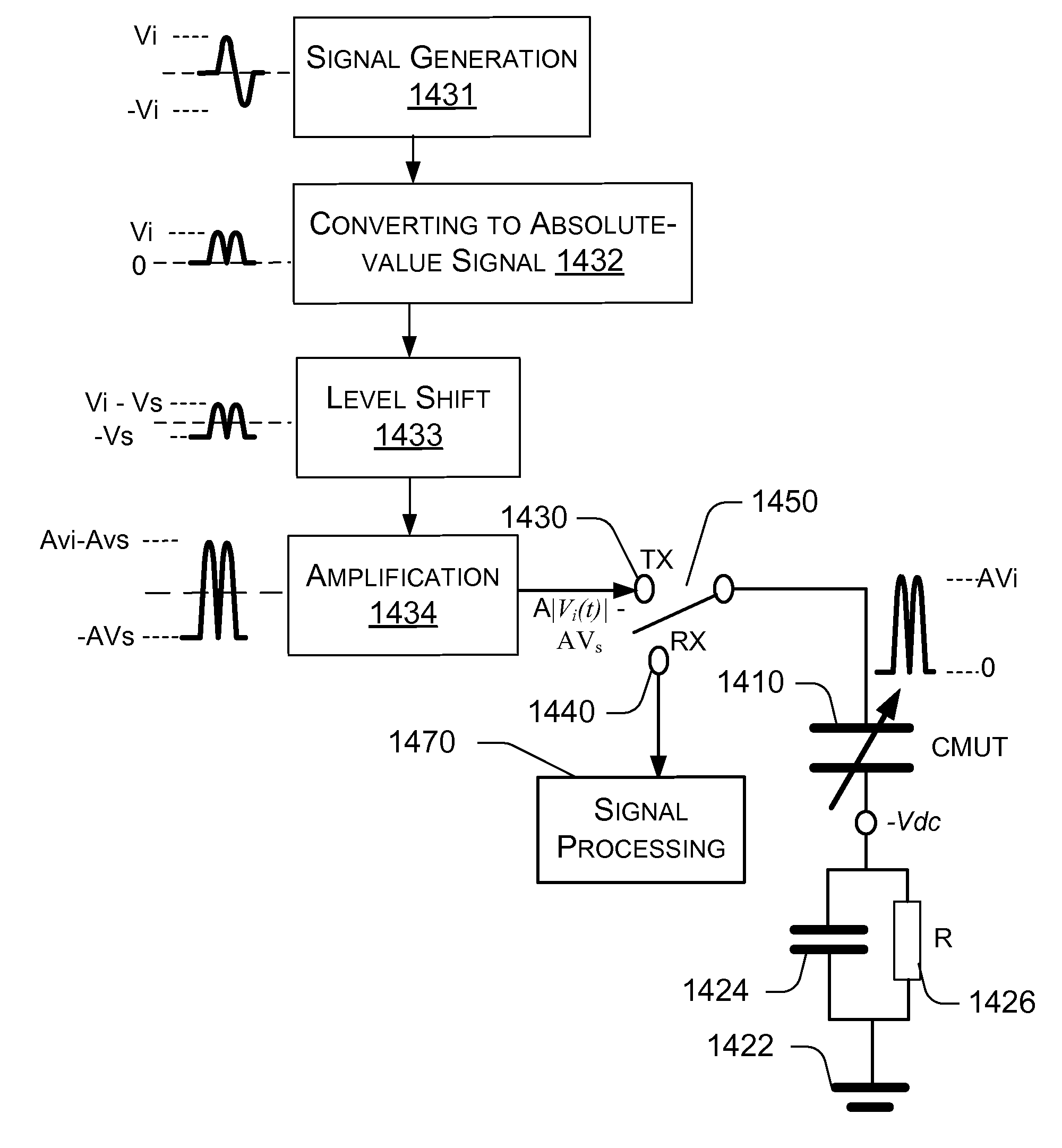
[0036]The micromachined ultrasonic transducer using signal control methods for reducing harmonic distortion of the output signal are described in detail along with the figures, in which like parts are denoted with like reference numerals or letters. The methods are adapted for transmitting an ultrasonic signal and / or receiving a pressure signal using a cMUT system.

[0037]CMUT Configurations for Second-Order Frequency Method

[0038]FIG. 4 shows an exemplary cMUT with an unmixed AC transmission input signal without a DC bias signal in the transmission mode. The setup includes cMUT 410 which is represented by a variable capacitor. One electrode 410a of the cMUT 410 is connected to transmission (TX) port 430 and reception (RX) port 440. Switch 450 is used to switch the line between the transmission port 430 and the reception port 440. An AC transmission input signal Vtx(t) is generated by AC signal source 432 and applied at the transmission input signal port 430, which may be a separate po...


PUM

PropertyMeasurementUnit
frequencyaaaaaaaaaa
frequency ω0aaaaaaaaaa
DC bias voltageaaaaaaaaaa

Abstract

A capacitive micromachined ultrasonic transducers (cMUT) uses signal control methods to reduce harmonic distortion of the output signal. The method uses an AC transmission input signal characterized with a frequency ω and takes the second-order frequency component with frequency 2ω, rather than the first-order frequency component with the base frequency ω, as the desired output pressure signal. A frequency ω is preferably equal to ω0 / 2, where ω is the desired cMUT output frequency. Various examples of AC transmission input signals, in combination with or without a DC bias signal, that are suitable for producing a large second-order frequency component and small (ideally zero) first-order frequency component are disclosed.

Description

PRIORITY[0001]This application claims priority from U.S. Provisional Applications Ser. No. 60 / 744242, filed Apr. 4, 2006.BACKGROUND[0002]The present invention relates capacitive micromachined ultrasonic transducers (cMUT), particularly to methods for operating cMUT.[0003]Capacitive micromachined ultrasonic transducers (cMUTs) are electrostatic actuator / transducers, which are widely used in various applications. Ultrasonic transducers can operate in a variety of media including liquids, solids and gas. These transducers are commonly used for medical imaging for diagnostics and therapy, biochemical imaging, non-destructive evaluation of materials, sonar, communication, proximity sensors, gas flow measurements, in-situ process monitoring, acoustic microscopy, underwater sensing and imaging, and many others. In addition to discrete ultrasound transducers, ultrasound transducer arrays containing multiple transducers have been also developed. For example, two-dimensional arrays of ultraso...

Claims


Application Information

Patent Timeline
Patent Type & Authority Applications(United States)
IPC IPC(8): B06B1/06H01L41/00A61B8/00G01H17/00
CPCB06B1/0238Y10T29/49005G01N29/2406B06B1/0292
Inventor HUANG, YONGLI
Owner KOLO MEDICAL (SUZHOU) CO LTD
Why Eureka
Try Eureka