Shutter for closing openings with pivotal shutter elements

a shutter element and shutter technology, applied in the direction of wing accessories, transportation and packaging, propulsion parts, etc., can solve the problems of inability to efficiently minimize cooling losses by thermal conduction or radiation, difficult to achieve a reliable seal therewith, and additional losses caused by thermal conduction and radiation

Inactive Publication Date: 2005-02-15
AVL LIST GMBH
View PDF28 Cites 112 Cited by
  • Summary
  • Abstract
  • Description
  • Claims
  • Application Information

AI Technical Summary

Benefits of technology

It is the object of the present invention to avoid these drawbacks and to develop a shutter or a shutter system that is provided with the best possible thermal values. More specifically, it is intended to find advantageous application in vehicles with thermal encapsulation of the engine where experience has shown that the control units for incoming and outgoing air constitute the weakest point.

Problems solved by technology

Although a shutter having a structure as described herein above is suited to largely inhibit air flow in its closed position, it is difficult to achieve a reliable seal therewith.
Furthermore, additional losses occur by thermal conduction and radiation.
Similar disadvantages are found in the device for regulating an air flow as it is described in DE 197 42 730 A1.
However, cooling losses by thermal conduction or radiation cannot be efficiently minimized with a device of this type.
The disadvantage of this shutter element is the poor acoustic insulation and the cooling loss by thermal conduction or radiation in the closed position.

Method used


Image

  • Shutter for closing openings with pivotal shutter elements
  • Shutter for closing openings with pivotal shutter elements
  • Shutter for closing openings with pivotal shutter elements

Examples


Embodiment Construction

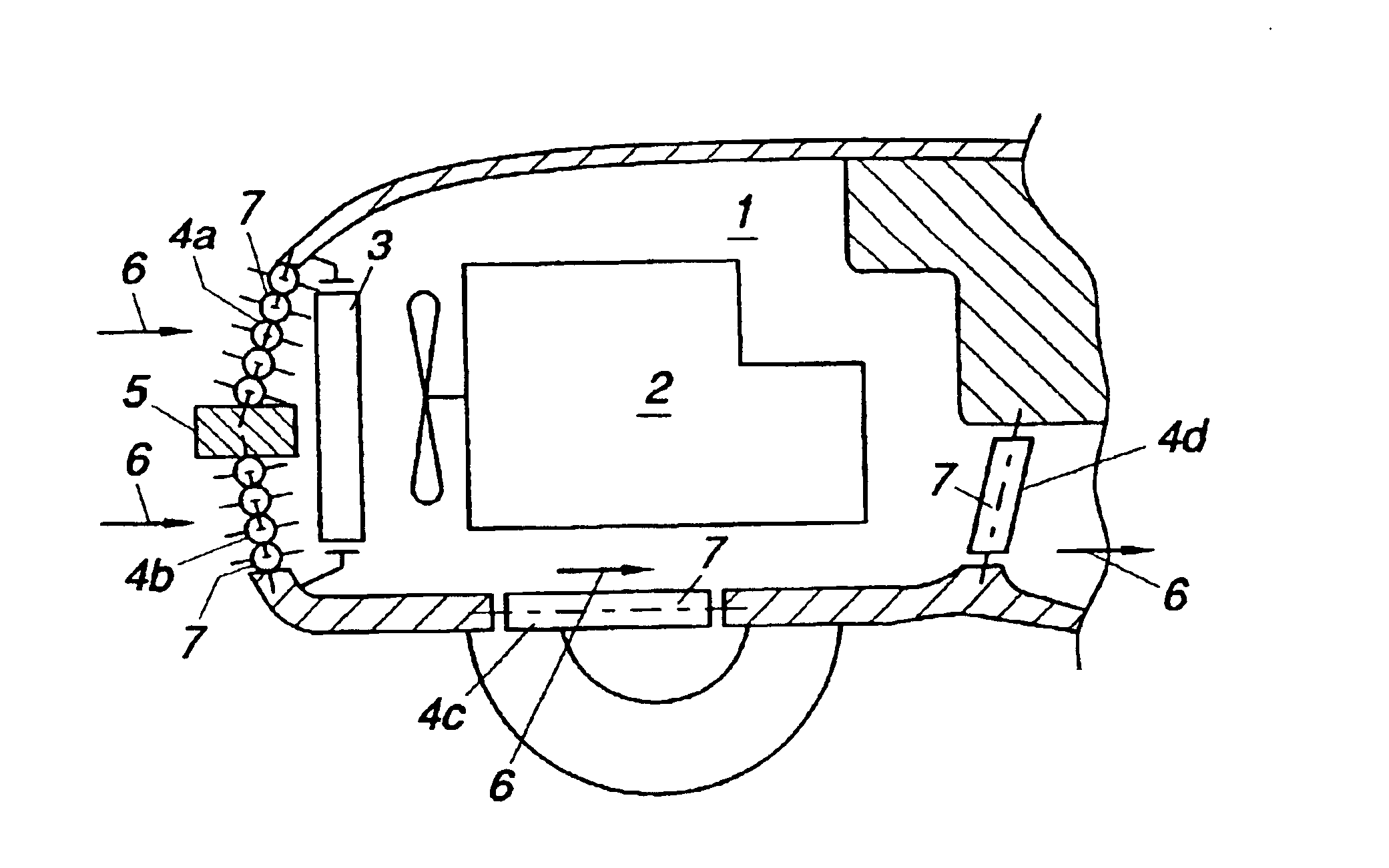
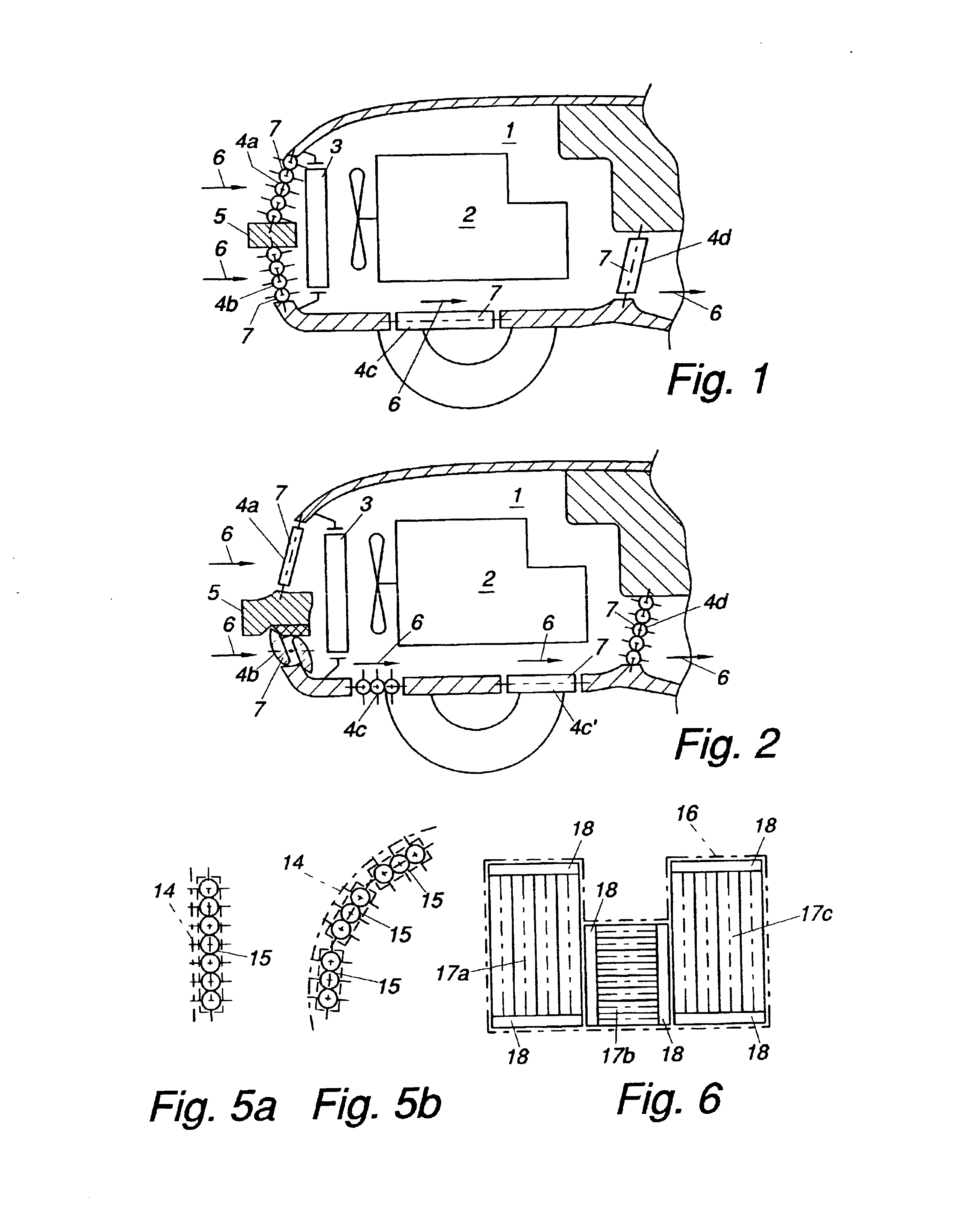
FIGS. 1 and 2 illustrate a detail of the engine compartment 1 of a vehicle that is not shown in detail herein and that accommodates an internal combustion engine 2, both showing possible examples of how to arrange the shutters of the invention. Air is flown through the radiator 3 of the internal combustion engine 2 via first and second openings 4a, 4b arranged above or underneath a bumper 5. Outgoing air leaves the engine compartment through opening 4d. The respective ones of the openings 4c (FIG. 1) and 4c and 4c′ (FIG. 2) may represent cross-sections for both incoming and outgoing air.

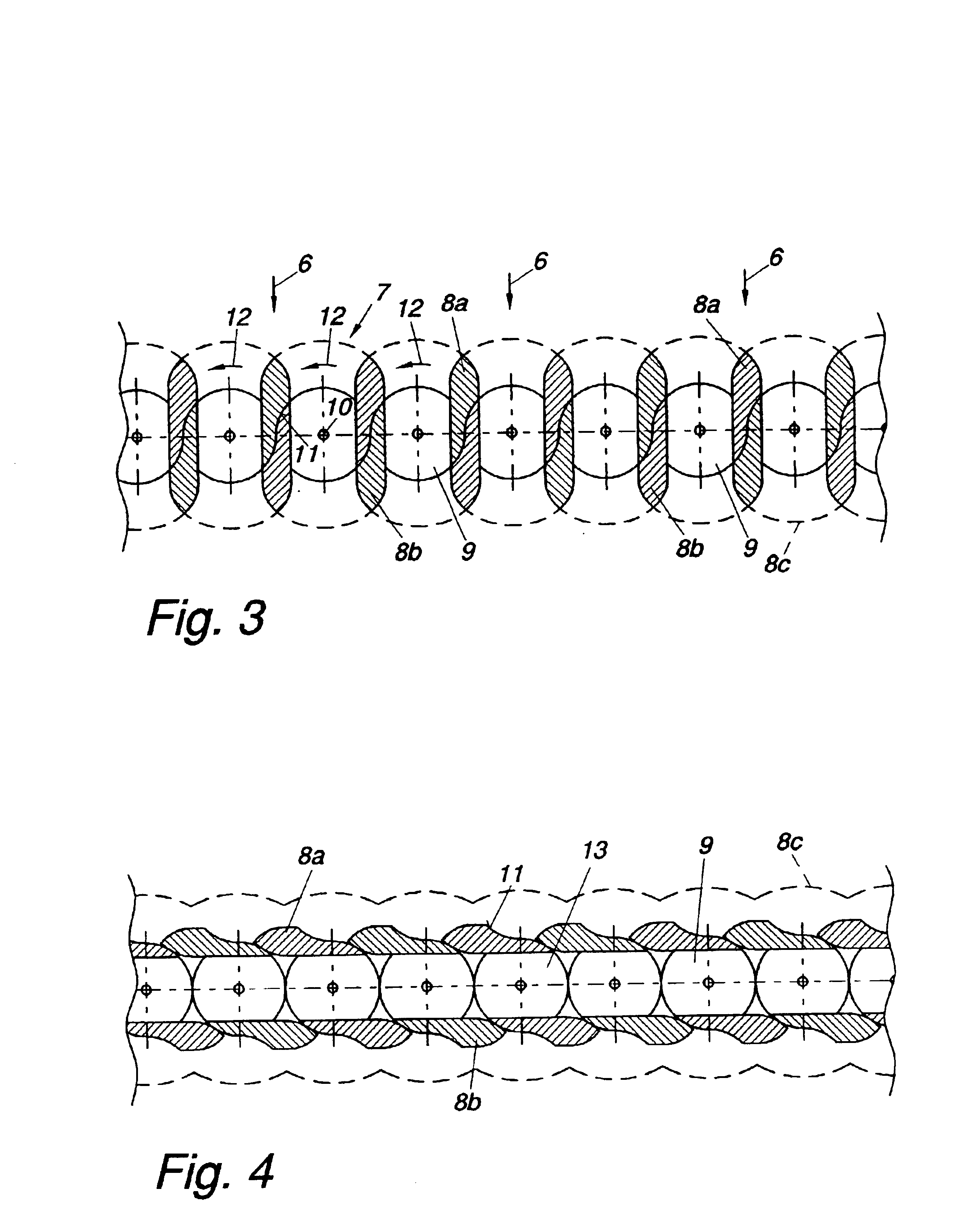
In FIG. 1, the clear cross-sections of the two incoming air openings 4a and 4b may be regulated by means of a shutter provided with shutter elements 7 that are oriented horizontally transversely to the direction of flow (arrows 6). The same applies for the openings 4c and 4d (the opening 4d at least constituting an opening for outgoing air) except that here, the shutter elements 7 or the slats of the...


PUM


Abstract

A shutter for closing openings with pivotal shutter elements, the rotational axes of which are arranged parallel to each other. Better sealing is achieved in that the shutter elements consist of at least two wings that are solidly joined together and arranged almost parallel to each other. The wings of the shutter elements are oriented substantially parallel to an imaginary plane of the opening, thus closing it on both sides, in a first position and substantially normal to the plane of the opening, thus clearing said opening, in a second position.

Description

BACKGROUND OF THE INVENTIONThe invention relates to a shutter for closing openings with pivotal shutter elements, the rotational axes of which are arranged parallel to each other.DESCRIPTION OF PRIOR ARTShutters in the form of Venetian blinds are mainly used to let in more or less light into a room. If the slats are provided with sufficient rigidity, such Venetian blinds may also be used to perform a change in the ventilation of buildings, vehicles or the like. An appropriate opening is thereby closed by the slats in one position. In rotating the slats about 90° on paralleled axes, the opening may be cleared to allow free air flow. A shutter of this type is described in EP 0 163 986 A and is provided for covering the radiator of an internal combustion engine for the purpose of controlling the temperature of the engine.Although a shutter having a structure as described herein above is suited to largely inhibit air flow in its closed position, it is difficult to achieve a reliable sea...

Claims


Application Information

Patent Timeline
Patent Type & Authority Patents(United States)
IPC IPC(8): B60K11/00B60K11/08E06B7/084E06B7/02
CPCB60K11/085B60L8/006E06B7/084Y02T10/7083Y02T10/7072Y02T10/88
Inventor VIDE, MARKO-DEJAN
Owner AVL LIST GMBH
Why Eureka
Try Eureka