Shock absorber

a technology of shock absorber and tubular member, which is applied in the direction of shock absorbers, elastic dampers, roofs, etc., can solve the problems of insufficient prevention of the inclination of the smaller-diameter tubular portion, inability to absorb impact energy, and tilting and bending of the smaller-diameter tubular member on the flat surface of the step portion, etc., to achieve the effect of lowering the pressur

Inactive Publication Date: 2005-02-15
ASTEER
View PDF16 Cites 36 Cited by
  • Summary
  • Abstract
  • Description
  • Claims
  • Application Information

AI Technical Summary

Benefits of technology

Moreover, it is advisable that the guiding member forms the larger-diameter annular guiding portion as an annular outward-curled edge portion by curling back the smaller-diameter annular guiding portion protruding from the smaller-diameter tube portion into the larger-diameter tube portion toward the smaller-diameter tube portion so much as to contact to the inner surface of the larger-diameter tube portion. Either, the guiding member forms the larger-diameter annular guiding portion as an annular folded-inward edge portion by expanding the smaller-diameter annular guiding portion protruding from the smaller-diameter tube portion into the larger-diameter tube portion so much as to contact to the inner surface of the larger-diameter tube and by folding back the smaller-diameter annular guiding portion radially inward of the larger-diameter tube portion. By thus curling to construct the larger-diameter annular guiding portion, the structural strength resisting to the impact applied obliquely of the axial direction can be given to the larger-diameter annular guiding portion.
Moreover, it is advisable that the guiding member has a tubular ring portion formed in the larger-diameter annular guiding portion and contacting with the inner surface of the larger-diameter tube portion. The tubular ring portion to contact with the inner surface of the larger-diameter tube portion over a wide area lowers the pressure (i.e., the impulsive force / the contact area) due to the impact applied obliquely of the axial direction, thereby to intensify the action of the guiding member to prevent or retain the inclination of the smaller-diameter tube portion. This tubular ring portion basically takes a shape similar to that of the larger-diameter tube portion because it contacts with the inner surface of the larger-diameter tube portion. It is advisable that the aforementioned annular folded-inward edge portion is formed at the edge portion of the tubular ring portion.

Problems solved by technology

Thus, there arises a problem that the impact energy cannot be absorbed.
However, the action to prevent or to retain the inclination of the smaller-diameter tube portion utilized by the intermediate-diameter tube portion is restrictive (up to about 30 degrees in the axial direction) so that the prevention of the inclination of the smaller-diameter tube portion cannot be sufficiently achieved against an impact at a larger angle obliquely of the axial direction.
In the case of the offset load, however, there arises a problem that the smaller-diameter tubular member is inclined and bent on the step portion flat surface.

Method used


Image

  • Shock absorber
  • Shock absorber
  • Shock absorber

Examples


Embodiment Construction

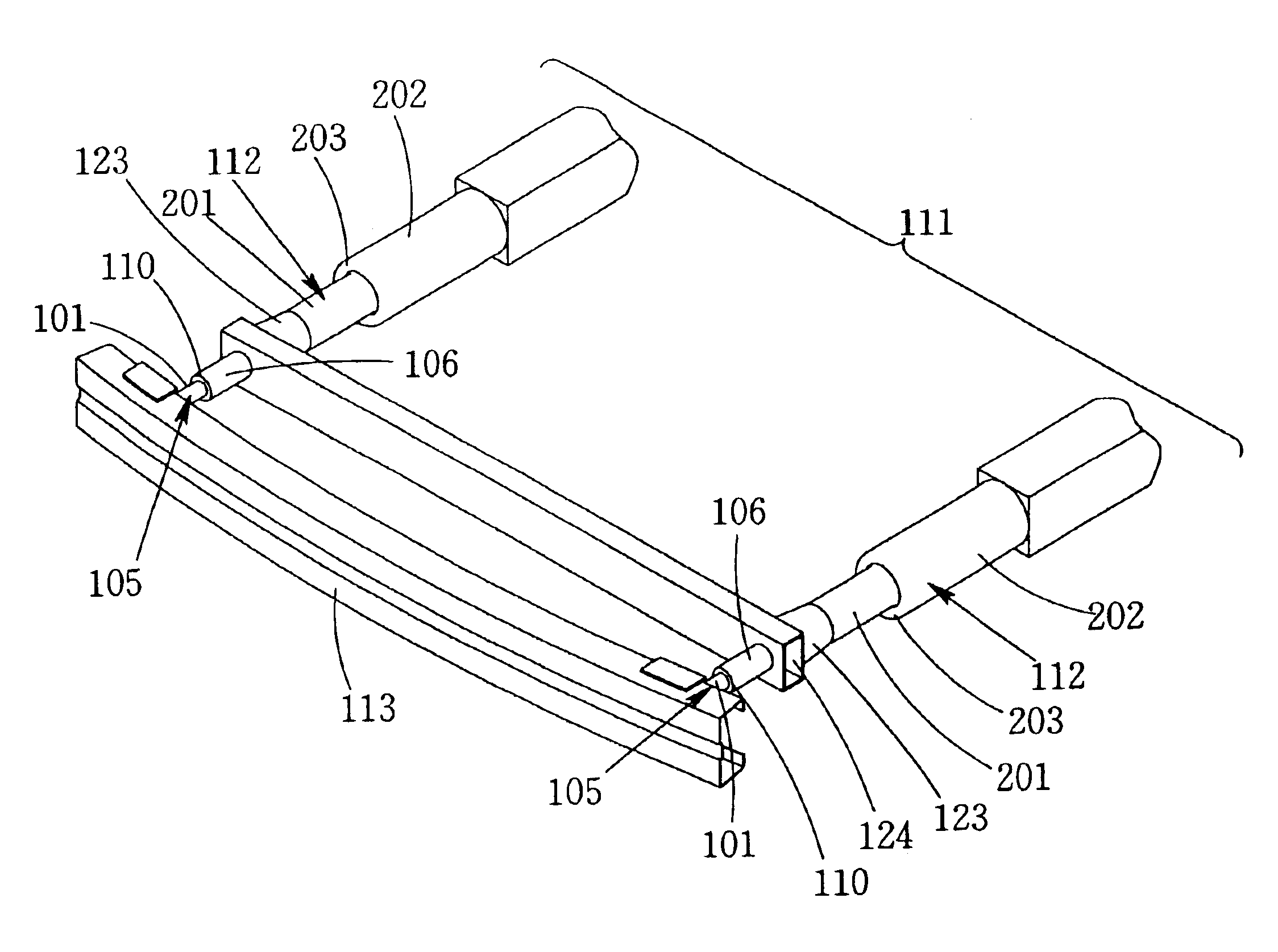
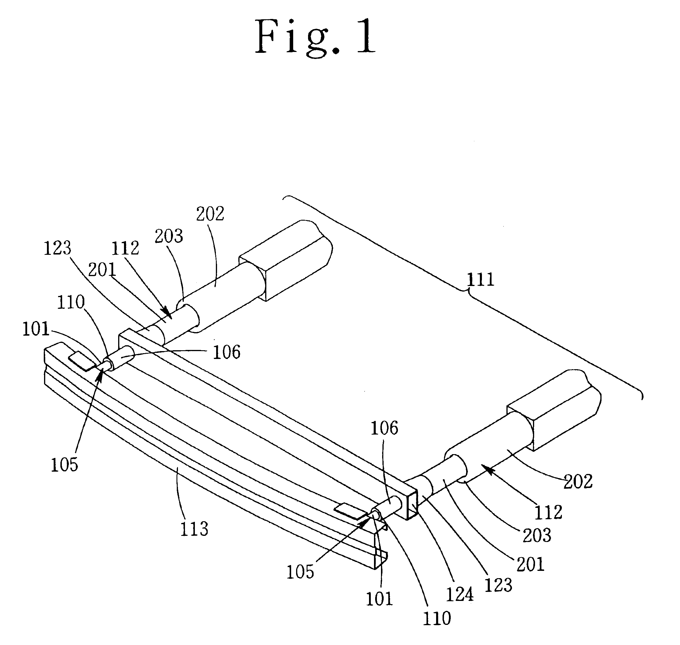
An embodiment of a shock absorber as being of a bumper supporting member will be described hereinafter with reference to the accompanying drawings.

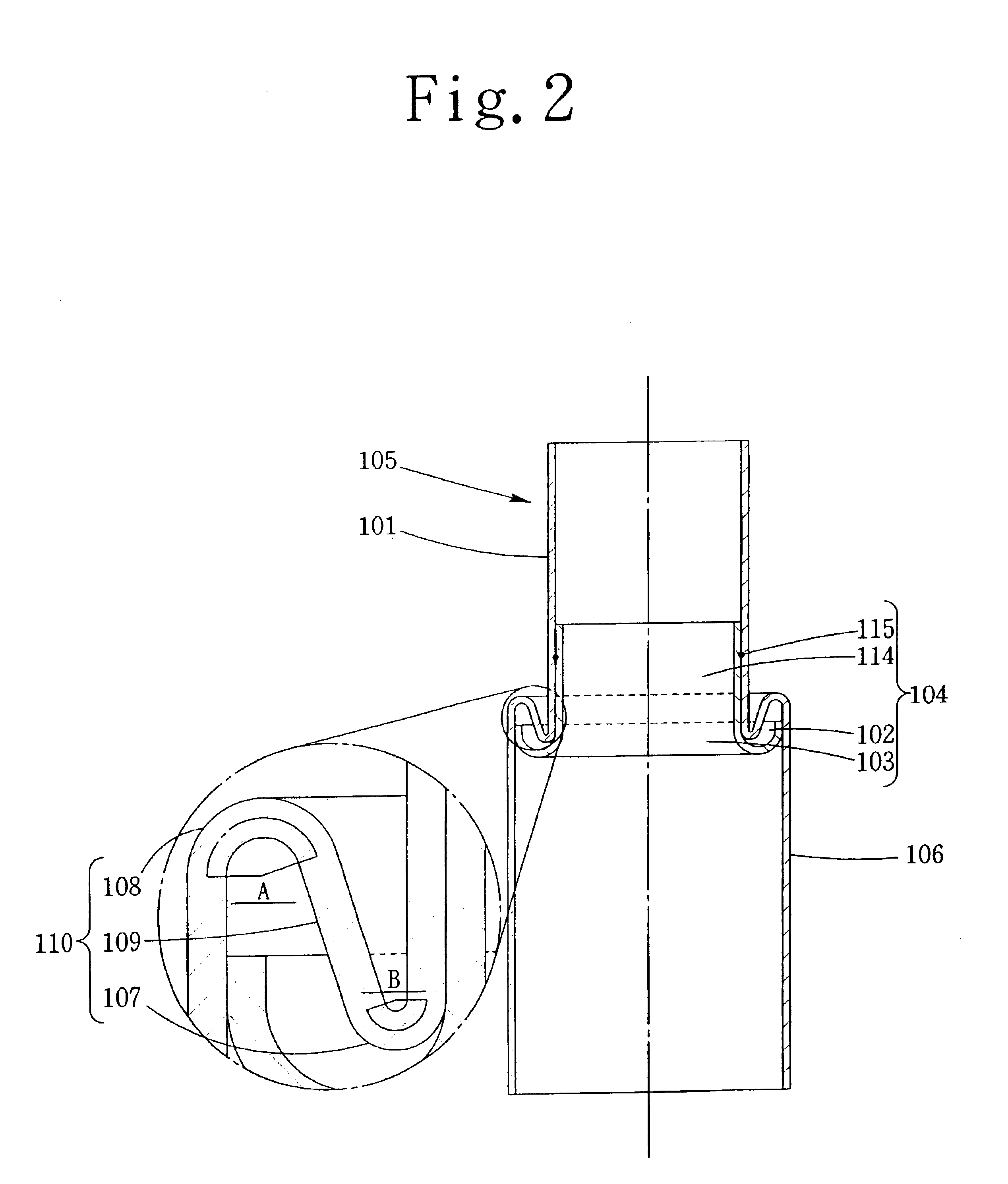
A shock absorber 105 as being of a bumper supporting member of this embodiment has a two-step tubular structure comprising a smaller-diameter tube portion 101 and a larger-diameter tube portion 106 integrally formed through a step portion 110 by partially reducing or partially enlarging a diameter of a plastically deformable straight tube, as shown in FIG. 2. In this embodiment, the smaller-diameter tube portion 101 and the larger-diameter tube portion 106 are axially shrunken in the axial direction (as referred to a single-dotted line in FIG. 2 as in the following) to form a step portion 110 of an S-shaped section joining a folded-back portion 107 of the smaller-diameter tube portion having a section of a smaller radius B of curvature and a folded-back portion 108 of the larger-diameter tube portion having a section of a larger radius A ...


PUM


Abstract

A shock absorber as being of a bumper supporting member and a shock absorber as being of a side member, which retain the sinking motion of a smaller-diameter tube portion into a larger-diameter tube portion even if an impact is applied at a larger angle obliquely of an axial direction, thereby to achieve the absorption of the impact energy by a plastic deformation. A plastically deformable straight tube is partially reduced or partially enlarged to form a smaller-diameter tube portion and a larger-diameter tube portion, which join to each other through a step portion. The step portion is formed by joining a folded-back portion of the smaller-diameter tube portion and a folded-back portion of the larger-diameter tube portion, which have circular arc-shaped sections having arcuate angles more than 90 degrees.

Description

BACKGROUND OF THE INVENTION1. Field of the InventionThe present invention relates to a shock absorber for absorbing an impact energy as a plastic deformation-generating energy and, more particularly, to a shock absorber adapted to be used either as a side member constructing a vehicle frame member side portion of an automobile or as a bumper supporting member for absorbing the impact energy applied to the bumper of the automobile thereby to prevent or retain the transmission of the impact energy to the vehicle frame member.2. Description of the Related ArtIn a vehicle such as an automobile, shock absorbers are used at many portions for absorbing the impact energy as the plastic deformation-generating energy so as to protect the passenger against an impact when the vehicle collides. For example, the shock absorber (as will be called the “shock absorber as being of a bumper supporting member”) is used as the bumper supporting member, which includes tubular bodies for supporting the bu...

Claims


Application Information

Patent Timeline
Patent Type & Authority Patents(United States)
IPC IPC(8): B60R19/24B60R19/34F16F7/12
CPCF16F7/125B60R19/34
Inventor YOSHIDA, HIROSHIGOTO, HIROSHISHIMOTSU, KOJI
Owner ASTEER
Why Eureka
Try Eureka