Play media shooting machine with improved stop control

a technology of stop control and media shooting machine, which is applied in the field of game machines, can solve the problems of increasing player frustration and little room left for reflecting player's intention, and achieve the effect of reducing player's labor

Inactive Publication Date: 2005-02-15
SANKYO CO LTD
View PDF22 Cites 22 Cited by
  • Summary
  • Abstract
  • Description
  • Claims
  • Application Information

AI Technical Summary

Benefits of technology

The present invention has been made to solve the foregoing problems. An object of the present invention is to provide a game machine that allows a player to play a game in a manner reflecting the player's intention to the utmost, while reducing the player's labor.
According to the present invention, the shooting operation of the play media is started by an input from a user to start shooting the play media. Thus, it is unnecessary to control shooting of every play medium, which alleviates the player's labor required to play the game. Further, the shooting of the play media can be stopped any time in accordance with the player's intention.

Problems solved by technology

It however has a disadvantage that, since the balls are shot off continuously until a predetermined number of balls are all flipped, little room is left for reflecting the player's intention.
Failure to choose such a desired timing would increase the player's frustration.

Method used


Image

  • Play media shooting machine with improved stop control
  • Play media shooting machine with improved stop control
  • Play media shooting machine with improved stop control

Examples


first embodiment

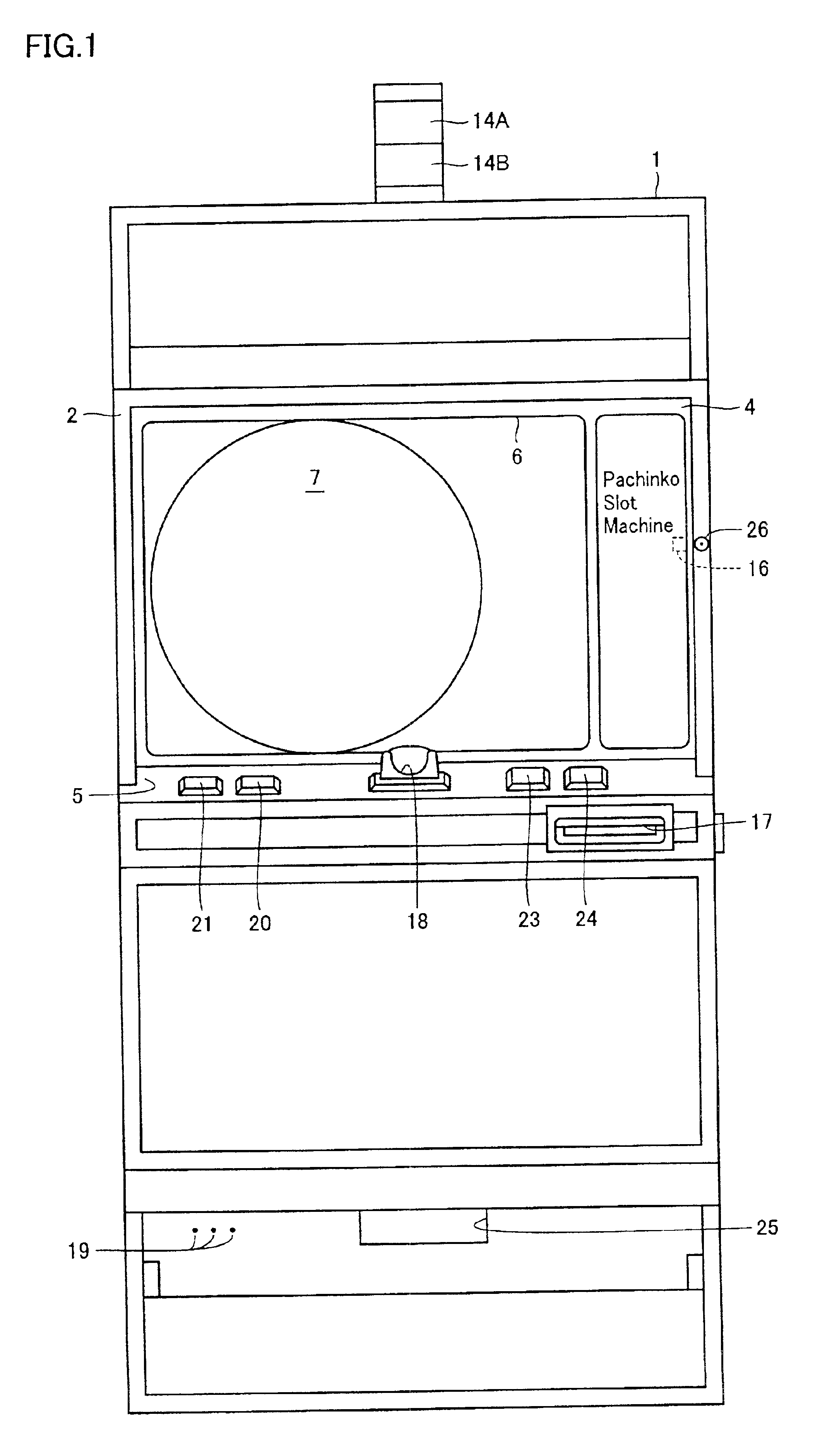
FIG. 1 is an entire front view showing an image display type game machine 1 as an example of the game machine according to the present invention.

A front frame 2 is provided in game machine 1. A glass door frame (metal frame) 4 and a front cover plate 5 are provided to front frame 2 in such a manner that they can be opened / closed freely. An image display region 6 is formed of an image display of a CRT display device, for example, that is mounted to game machine 1 at the middle of its backside. Image display region 6 is covered with a touch screen 60 (see FIG. 2), as will be described later.

A key hole 26 is provided in front frame 2. When an attendant of the game hall inserts a prescribed key into key hole 26 and turns it to the left in the drawing, glass door frame 4 is unlocked and attains an openable state. Opening of glass door frame 4 is detected by a metal frame opening switch 16.

A coin selector and a coin sorter (both not shown) are provided at the backside of front cover plate...

second embodiment

The second embodiment of the present invention will now be described with reference to FIGS. 11-13. Here, a modification of image display type game machine 1 described as the first embodiment above will be explained.

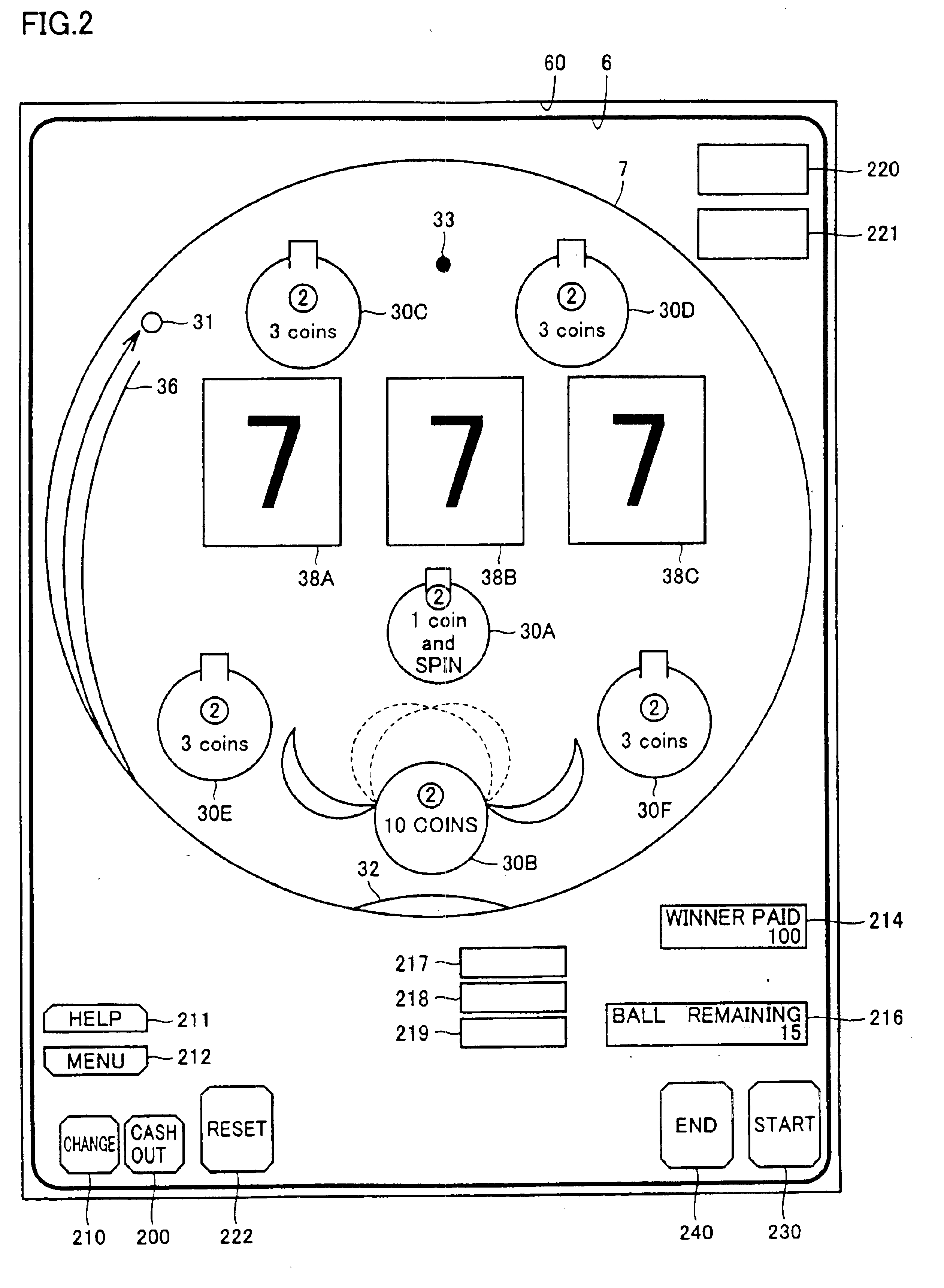
The entire front view of the game machine 10 according to the second embodiment is shown in FIG. 11, in which the same components as in the game machine 1 shown in FIG. 1 are denoted by the same reference characters, and description thereof will not be repeated here.

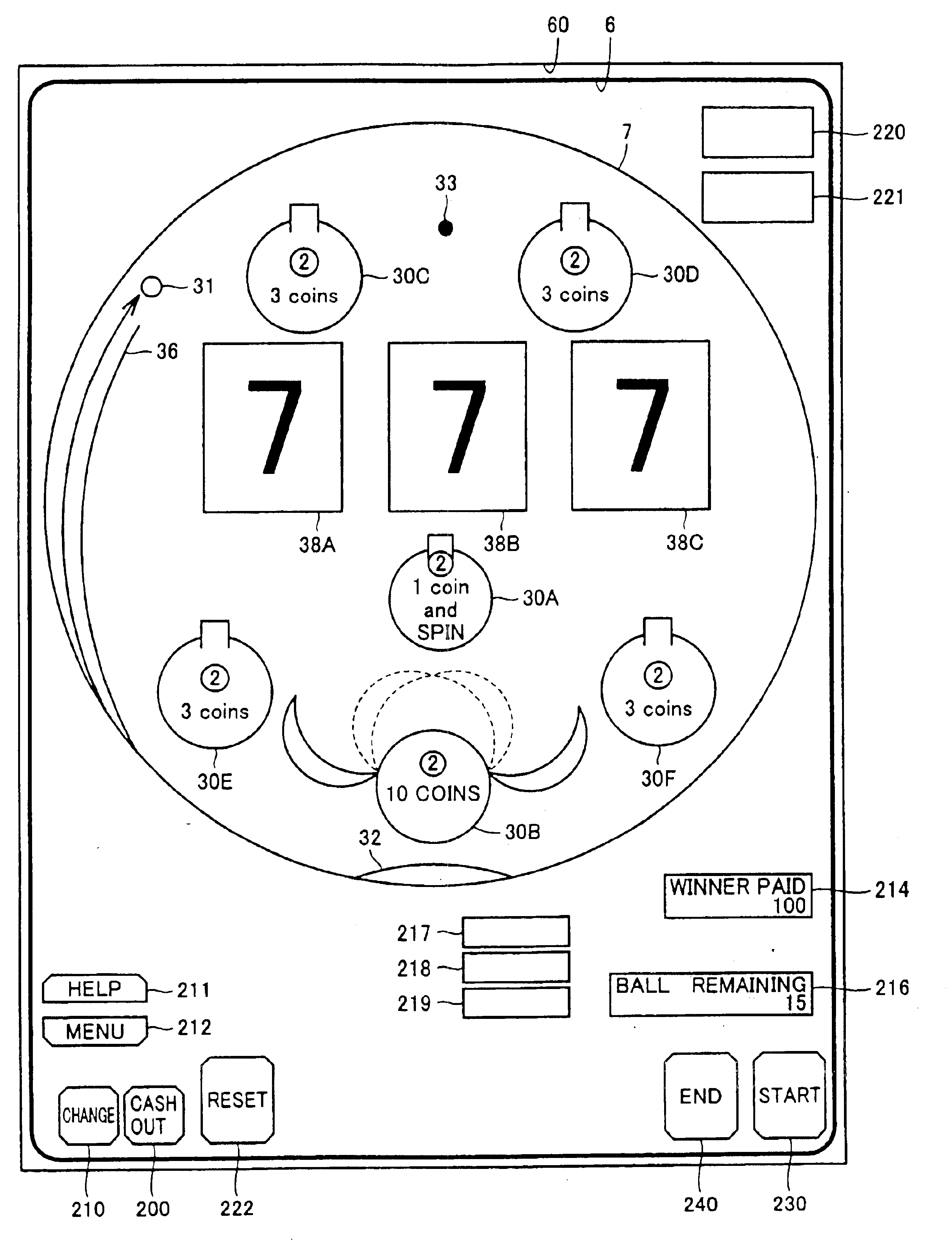
The game machine 10 of the second embodiment is identical to game machine 1 of the first embodiment shown in FIG. 1 in that it is provided with touch screen 60 covering image display region 6 (see FIG. 12). A player is allowed to manipulate touch screen 60 to call the menu screen as shown in FIG. 3 and to select one of various play board screens as desired. FIGS. 12 and 13 show by way of example two play board screens selectable by the player.

Game machine 10 of the second embodiment differs from game machine ...

third embodiment

The third embodiment of the present invention will now be described with reference to FIGS. 14 and 15. In the first and second embodiments, the image display type game machine having the play field, balls, winning holes and others all displayed as images has been described. However, the present invention is also applicable to a game machine employing actual balls, as described hereinafter as the third embodiment.

FIG. 14 is a front view of the play field 70 in the case where the present invention is applied to a game machine in which actual balls are flipped. This play field 70 is provided, e.g., on a play board installed in a frame of the game machine. Play field 70 includes a guide rail 360 for guiding a flipped ball 310 to the upper portion of play field 70, reels 380A, 380B, 380C, six winning holes 300A-300F, a lost ball port 320, a great number of obstructive nails 330 (of which one nail 330 is representatively shown), and others. Of the plurality of winning holes, winning hole ...


PUM


Abstract

The game machine includes a start detection unit for detecting an input from a user to start shooting balls, a shooting control unit for initiating shooting the balls in response to the start detection unit detecting the relevant input from the user and for controlling to stop shooting the balls in response to all the available balls having been shot, and a stop detection unit for detecting an input from the user to stop shooting the balls. The control unit controls to stop shooting the balls in response to the stop detection unit detecting the relevant input from the user. Thus, manipulability for shooting balls is improved. Further, a game well reflecting the player's intention to stop shooting the balls is provided.

Description

BACKGROUND OF THE INVENTION1. Field of the InventionThe present invention relates to game machines such as Pachinko game machines and coin game machines, and more particularly to a game machine provided with a casing and a play field including a winning region into which a play medium can enter to achieve a win.2. Description of the Background ArtAs a conventional game machine of the above-described type, the game machine wherein balls are flipped into a play field upon manipulation of a start button is known. The game machine of this type has an advantage that a player does not need to adjust strength of the shooting, thereby reducing the player's labor.It however has a disadvantage that, since the balls are shot off continuously until a predetermined number of balls are all flipped, little room is left for reflecting the player's intention.In particular, the timing at which a player wants to stop shooting the balls to finish the game varies with the individual. Failure to choose s...

Claims


Application Information

Patent Timeline
Patent Type & Authority Patents(United States)
IPC IPC(8): G07F17/38G07F17/32
CPCG07F17/3297
Inventor YAMAGUCHI, SHINSUKE
Owner SANKYO CO LTD
Why Eureka
Try Eureka