Sealing structure for combustor liner

a combustor and liner technology, applied in the direction of efficient propulsion technologies, machines/engines, light and heating apparatus, etc., can solve the problems of large difference in thermal expansion coefficient between a cmc and a metal, difficulty in significantly reducing the amount of cooling air for the combustor liner, and large difference in thermal expansion coefficient between the combustor liner and the structure of the metallic material surrounding the combustor liner, etc., to achieve the effect o

Inactive Publication Date: 2005-02-15
KAWASAKI HEAVY IND LTD
View PDF24 Cites 53 Cited by
  • Summary
  • Abstract
  • Description
  • Claims
  • Application Information

AI Technical Summary

Benefits of technology

The present invention has been made in view of the aforementioned problems in the related art and it is therefore an object of the present invention to provide a sealing structure for sealing a gap around a combustor liner, capable of absorbing the difference in thermal expansion between the combustor liner and an associated surrounding structure and of satisfactorily sealing the gap around the combustor liner.
The sealing structure of the present invention is capable of satisfactorily sealing the gap around the combustor liner without excessively loading the combustor liner even if the difference in thermal expansion between the combustor liner and the surrounding structure is large.

Problems solved by technology

In the case of the conventional combustor liner made of a metallic material having low heat resistance, it is difficult to significantly reduce the amount of cooling air for cooling the combustor liner.
However, since ceramic materials, in general, are brittle and have linear expansion coefficients smaller than those of metallic materials, the difference in thermal expansion between a combustor liner of a ceramic material and structures of metallic materials surrounding the combustor liner is large while the combustor operates under the condition of high temperature.
The difference in thermal expansion coefficient between a CMC and a metal is large, and a plate spring used for sealing the gap between a liner of a CMC and the associated surrounding structure of a metal needs to have a long length and needs a large space for installation.
Such requisite conditions for using a combustor liner of a CMC is very disadvantageous in applying the combustor liner to a gas turbine serving as an aircraft engine in which reduction of weight and space for installation is very important.
The dimensions of a large, long plate spring used for sealing the gap around the combustor liner of a CMC change greatly when the plate spring is heated and, consequently, the plate spring is unable to maintain a stable sealing function at high temperatures.
Therefore, when the plate spring is used for sealing the gaps around a combustor liner of a CMC that is heated at higher temperatures in comparison to a combustor liner of a metal, it is possible that the elasticity of the plate spring is lost due to creep and the sealing function of the plate spring is deteriorated in a short period of operation.

Method used


Image

  • Sealing structure for combustor liner
  • Sealing structure for combustor liner
  • Sealing structure for combustor liner

Examples


Embodiment Construction

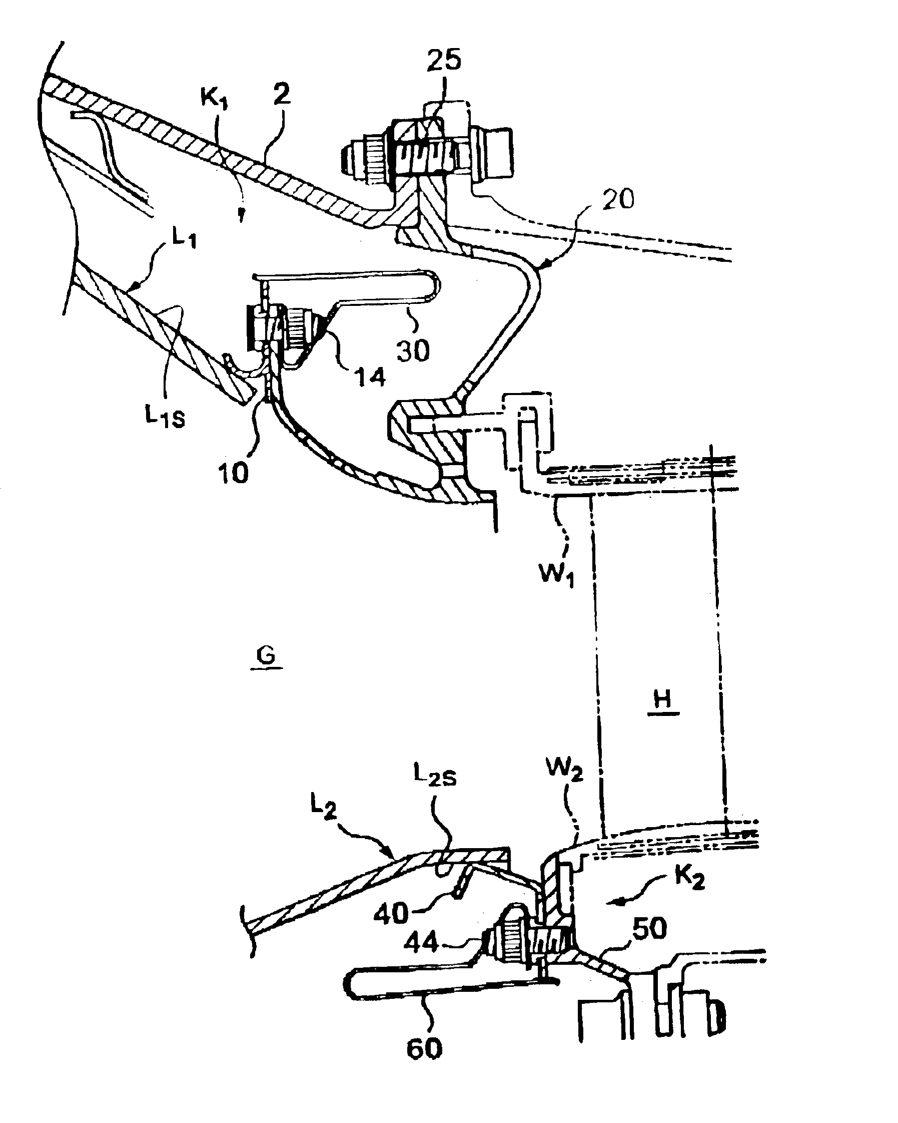
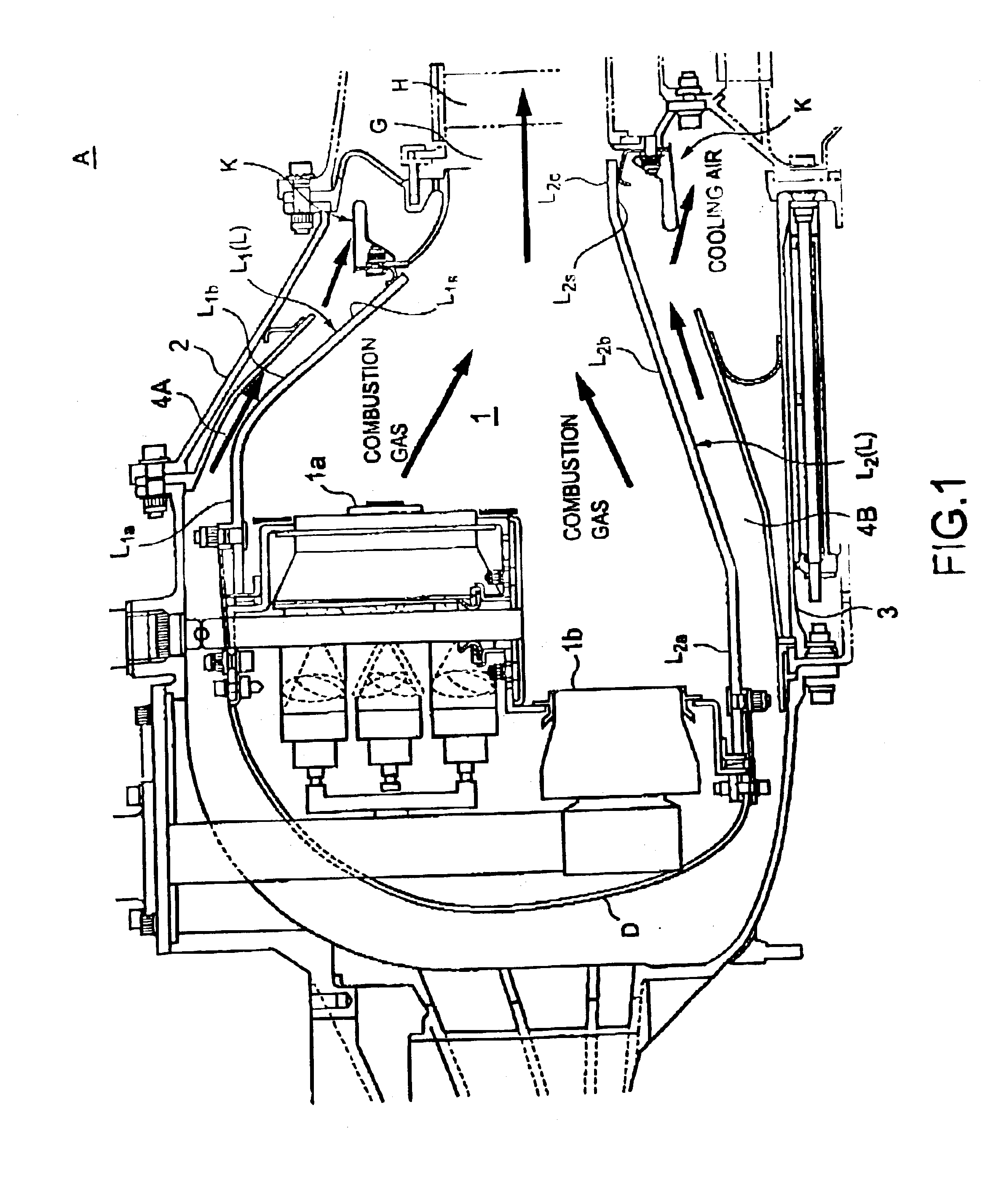
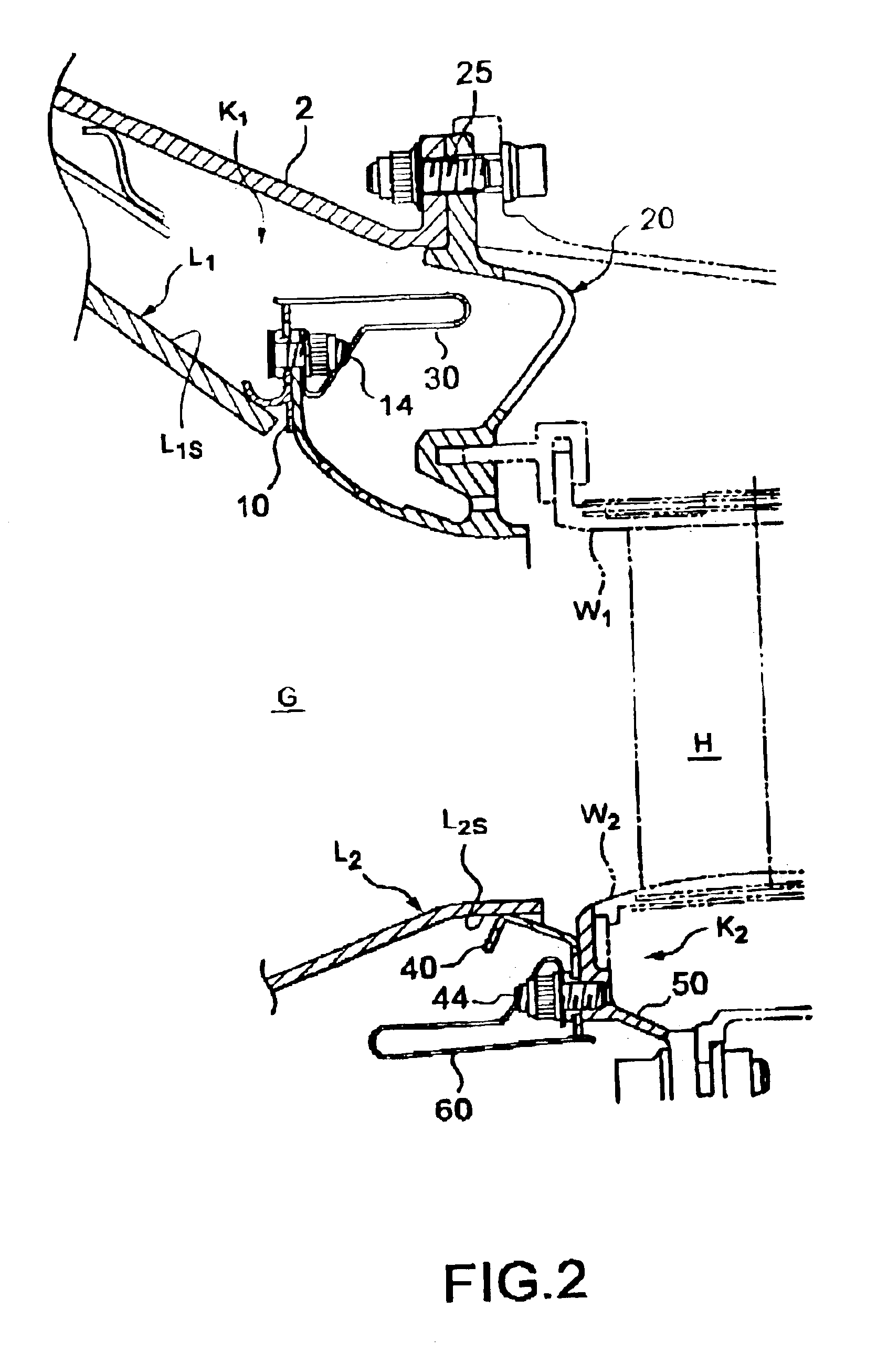
FIG. 1 shows a combustor A provided with a sealing structure in a preferred embodiment according to the present invention. The combustor A is an annular combustor included in a gas turbine as, for example, an aircraft engine. The combustor A has a toroidal combustion chamber 1, and includes an outer case 2, a combustor liner L, and an inner case 3.

Main burner units 1a and pilot burner units 1b are disposed in the-combustion chamber 1. The combustor liner L consists of an annular outer liner L1 and an annular inner liner L2 of a diameter smaller than that of the outer liner L1. The liners L1 and L2 are formed of a ceramic material, such as a CMC, i.e., a fiber-reinforced composite ceramic material. The combustion chamber 1 is defined by the outer liner L1, the inner liner L2, and a dome D of a metal joined to the ends of the liners L1 and L2. An outer cooling air passage 4A is defined by the outer case 2 and the outer liner L1, and an inner cooling air passage 4B is defined by the in...


PUM


Abstract

A sealing structure for sealing a gap between a combustor liner having an outer surface and a surrounding structure surrounding the combustor liner, includes: an annular sealing member held on the surrounding structure so as to be in contact with the outer surface of the combustor liner. The sealing member includes a plurality of sealing segments arranged in an annular configuration. The sealing structure seals the gap around the combustor liner of the combustor and absorbs, the difference in thermal expansion between the combustor liner and the surrounding structure.

Description

BACKGROUND OF THE INVENTION1. Field of the InventionThe present invention relates to a sealing structure for sealing a gap around a combustor liner. More specifically, the present invention relates to a sealing structure for a sealing gap around a combustor liner for a gas turbine to be used as, for example, an aircraft engine.2. Description of the Related ArtDevelopment of ceramic materials, such as CMCs (ceramics matrix composites), superior in heat resistance in comparison to conventional metallic materials has made progress in recent years, and studies have been made to use such ceramic materials for forming combustor liners. In the case of the conventional combustor liner made of a metallic material having low heat resistance, it is difficult to significantly reduce the amount of cooling air for cooling the combustor liner. On the other hand, when a combustor liner made of a ceramic material having high heat resistance is used as a combustor, it is possible to reduce the amount...

Claims


Application Information

Patent Timeline
Patent Type & Authority Patents(United States)
IPC IPC(8): F01D11/00F01D9/02F02C7/28F23R3/50F23R3/60F23R3/00F16J15/08F23R3/42
CPCF01D9/023F01D11/005F02C7/28F23R3/50F23R3/60F16J15/0887Y02T50/675Y02T50/672Y02T50/60
Inventor MATSUDA, YOSHIHIROKOBAYASHI, MASAYOSHIYOSHIMURA, TAKANOBUMIYAMOTO, HIROAKI
Owner KAWASAKI HEAVY IND LTD
Why Eureka
Try Eureka