Optical device and projector

a technology of optical devices and projectors, applied in the field of optical devices, can solve problems such as the difficulty of fully showing the capabilities of liquid crystal panels, and achieve the effects of enhancing the cooling efficiency enhancing the cooling capabilities and high temperature of light modulating devices

Inactive Publication Date: 2005-02-15
SEIKO EPSON CORP
View PDF14 Cites 30 Cited by
  • Summary
  • Abstract
  • Description
  • Claims
  • Application Information

AI Technical Summary

Benefits of technology

The present invention addresses or solves the above problems, and accordingly, the invention provides an optical device that is capable of further enhancements in cooling capabilities, thereby contributing to reduced size, high luminance, and high reliability, of projectors.
Further, in the event that the projector includes an optical parts housing to store a plurality of optical elements making up an optical system, the optical parts housing is preferably configured of thermal-conductive material, and the base fixed to the optical parts housing. Further, in the event that the optical device and the optical parts housing are stored in an external case, the external case is preferably configured of thermal-conductive material, with the optical parts housing being joined with the external case in a thermally-conductible manner. According to such a configuration, the heat reaching the base through the holding member can be dissipated by thermal conduction to the optical parts housing, and in some instances, sequentially to the external case, so the cooling capabilities of the light modulating devices can be greatly enhanced. Accordingly, the cooling capabilities of the light modulating devices within the device are greatly enhanced, thereby achieving reduced size, high luminance, and high reliability, of projectors.

Problems solved by technology

However, reduction in size and increased luminance of projectors have recently become popular, and the thermal density within devices has increased as compared to related art arrangements, so heat dissipation measures within the projector, and particularly cooling of the liquid crystal panels, cannot be sufficiently carried out with structures primarily depending on only air paths for cooling the liquid crystal panels, and accordingly it has been difficult to fully exhibit the capabilities of the liquid crystal panels.

Method used


Image

  • Optical device and projector
  • Optical device and projector
  • Optical device and projector

Examples


first embodiment

The first embodiment according to the present invention will be described below with reference to the drawings.

(1. Primary Construction of Projector)

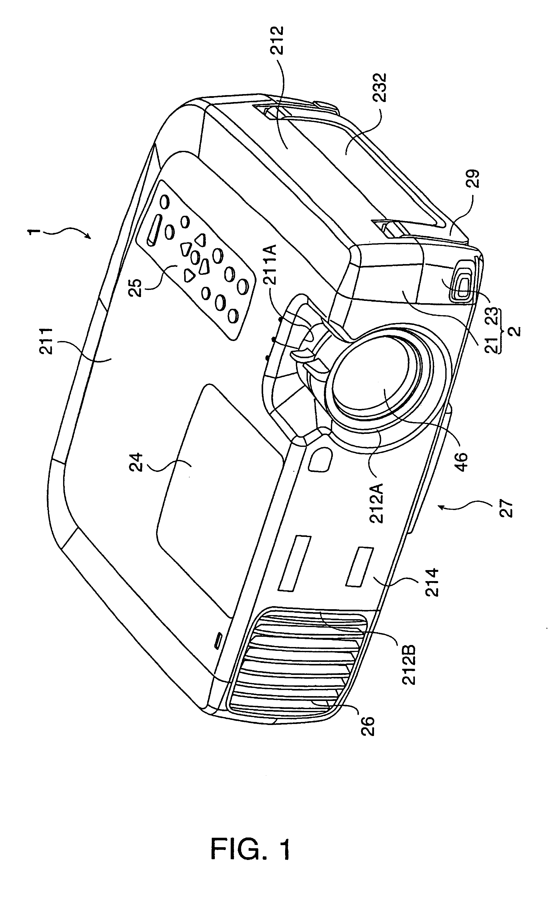
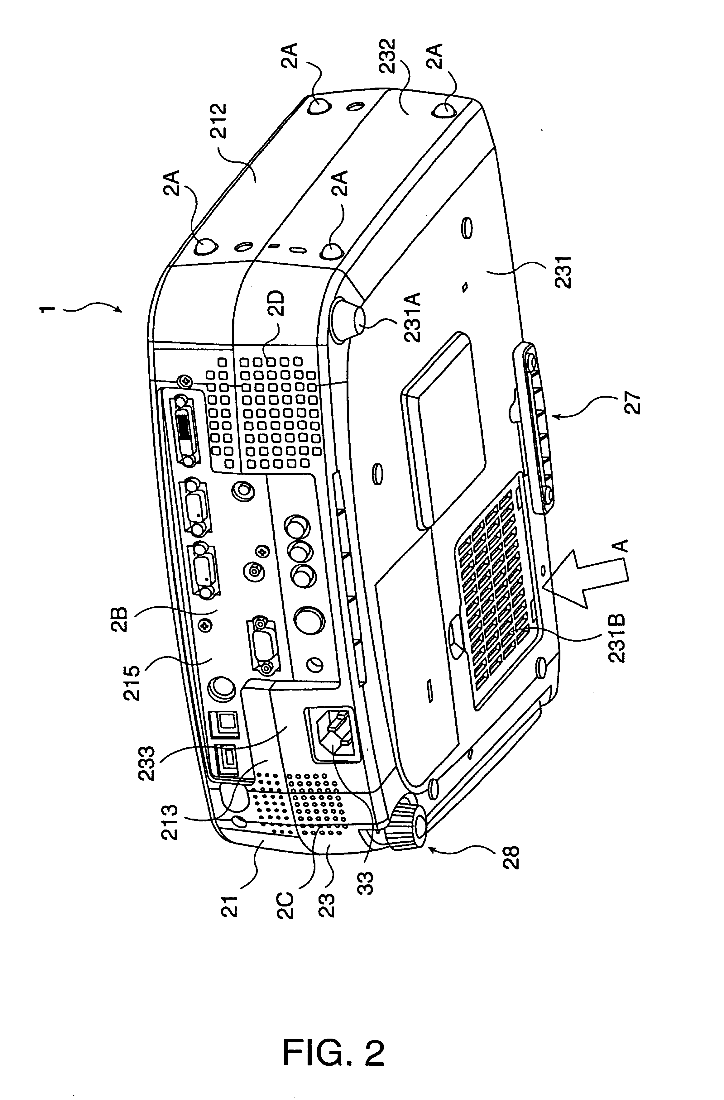
FIG. 1 is an overall perspective view of a projector 1 according to the first embodiment as viewed from above, FIG. 2 is an overall perspective view of the projector 1 as viewed from below, and FIG. 3 through FIG. 5 are perspective views of the interior of the projector 1. Specifically, FIG. 3 shows an upper case 21 of the projector 1 has been removed from the state shown in FIG. 1, FIG. 4 shows a shield plate 80, driver board 90, and upper housing 472 removed from the state shown in FIG. 3 as viewed from the rear side, and FIG. 5 shows an optical unit 4 has been removed from the state shown in FIG. 4. Elements 4, 21, 80, 90, and 472, which make up the projector, will be described below in detail.

In FIG. 1 through FIG. 5, the projector 1 has an external case 2, an electric power source unit 3 stored in the external case 2, and an optica...

third embodiment

The third embodiment according to the present invention will be described next.

In the following description, parts having the same structure as with the first embodiment are denoted with the same reference numerals, and detailed description thereof will be omitted or simplified.

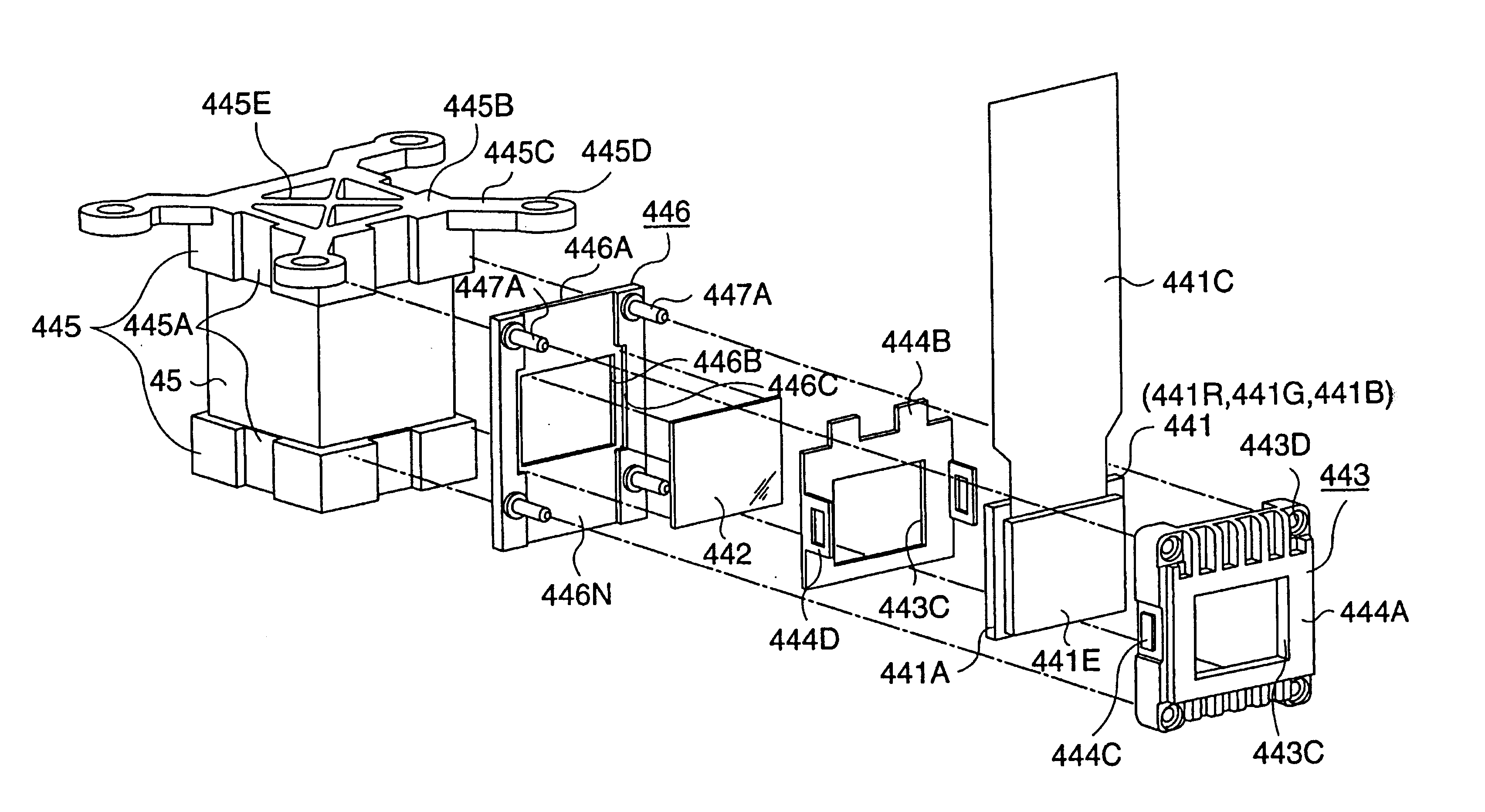
With the optical device according to the first embodiment, the holding member 446 had the rectangular plate-shaped member 446A, and pins 447A erected from the four corners of this rectangular plate-shaped member 446A. Conversely, the optical device according to the third embodiment differs in the point that the holding member 446 has erected pieces 447C with a general L-shape when viewed from the front, as shown in FIG. 16. Other configurations and manufacturing methods are the same as with the first embodiment. Also, for the materials of the components, such as those described with the first embodiment can be used.

Specifically, the erected pieces 447C are positioned at the corners of the rectangular plate-sh...

fourth embodiment

The fourth embodiment according to the present invention will be described next.

In the following description, parts having the same structure as with the first embodiment are denoted with the same reference numerals, and detailed description thereof will be omitted or simplified.

With the first embodiment, bases 445 were fixed to both the top and bottom faces of the cross-dichroic prism 45 (both of a pair of end faces intersecting the light flux incident end face), with the holding member 446 being fixed by adhesion to the side faces of the bases 445. Further, a polarizing plate 442 was fixed to engaging grooves 446C of the holding member 446 by double-face tape or an adhesive agent.

Conversely, with the fourth embodiment, the holding member 446 is fixed by adhesion to the light flux incident end face of the cross-dichroic prism 45, and also, the base 445 is provided on only one of the pair of end faces intersecting with the light flux incident end face of the cross-dichroic prism 45....


PUM


Abstract

The invention provides a structure to attach a liquid crystal panel to a prism, which enables further enhancements in cooling capabilities. The structure includes a storing member fixed on a base and holding a holding frame, where a liquid crystal panel is held. Erected pieces to form a space to receive the holding frame are formed protruding on both left and right sides at the light incident side. Protrusions to form an air path with a cross-dichroic prism are formed on both left and right sides on the light emitting side. The liquid crystal panel is attached to the cross-dichroic prism through a holding member having an opening at a portion corresponding to the panel face of the liquid crystal panel.

Description

BACKGROUND OF THE INVENTION1. Field of InventionThe present invention relates to an optical device where a light modulating device to modulate color light according to image information and a color synthesizing optical element to synthesize color light modulated by the light modulating device are integrally formed. The invention also relates to a projector employing the optical device.2. Description of Related ArtStructures for attaching liquid crystal panels and prisms in a projector are disclosed in, for example, Japanese Unexamined Patent Application Publication No. 2000-221587, Japanese Unexamined Patent Application Publication No. 2000-221588, and so forth. As disclosed in these publications, liquid crystal panels are stored within a panel frame and attached to a prism, thereby implementing measures to enhance the ease-of-assembly and the reliability of this part. Also, in the related art, cooling of the liquid crystal panel has been achieved by a structure that is almost compl...

Claims


Application Information

Patent Timeline
Patent Type & Authority Patents(United States)
IPC IPC(8): G03B21/00G02F1/13G02B7/18G02F1/1333G02F1/1335G03B21/14G03B21/16G03B21/20H04N5/74H04N9/31
CPCH04N9/3141H04N9/3144G03B21/145G03B21/006H04N9/3197G03B21/00
Inventor FUJIMORI, MOTOYUKIYANAGISAWA, YOSHIYUKIUEHARA, TAISUKEHASHIZUME, TOSHIAKIKITABAYASHI, MASASHIWATANABE, NOBUO
Owner SEIKO EPSON CORP
Why Eureka
Try Eureka