
Liquid drainage unit

Inactive Publication Date: 2005-02-15
EZFLOW
View PDF6 Cites 29 Cited by
  • Summary
  • Abstract
  • Description
  • Claims
  • Application Information

AI Technical Summary

Benefits of technology

Accordingly, a primary object of the invention is to provide a preassembled drainage line unit in which loose aggregate in the form of lightweight materials is contained within and bounded by a perforated conduit such as a plastic mesh tube of construction netting and wherein a barrier material overlies at least a portion of the aggregate to prevent solids from passing through the netting and entering the storage area defined by the aggregate.
The provision of the barrier material within the above described novel preassembled drainage units can be tailored to block the infiltration of outside media such as sand, dirt and soil through the net into the aggregate, to provide rigidity to the drainage units along their length and to provide structure which promotes the growth of microorganisms within the drainage unit.

Problems solved by technology

While those preassembled drainage line units have enjoyed commercial success, in certain applications problems have presented themselves.
For example depending on the type of fill soil placed on top of the preassembled units, solids such as sand or dirt may pass downwardly through the netting into the void area between adjacent aggregate, clogging that area and causing an undesirable reduction in liquid flow through the aggregate.

Method used


Image

  • Liquid drainage unit
  • Liquid drainage unit
  • Liquid drainage unit

Examples


Embodiment Construction

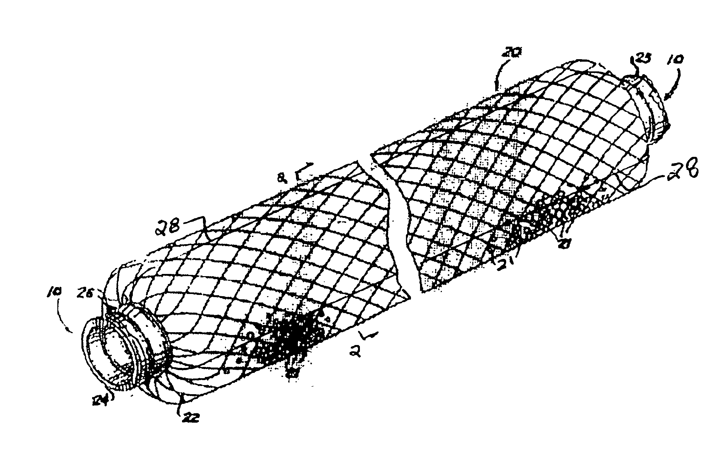
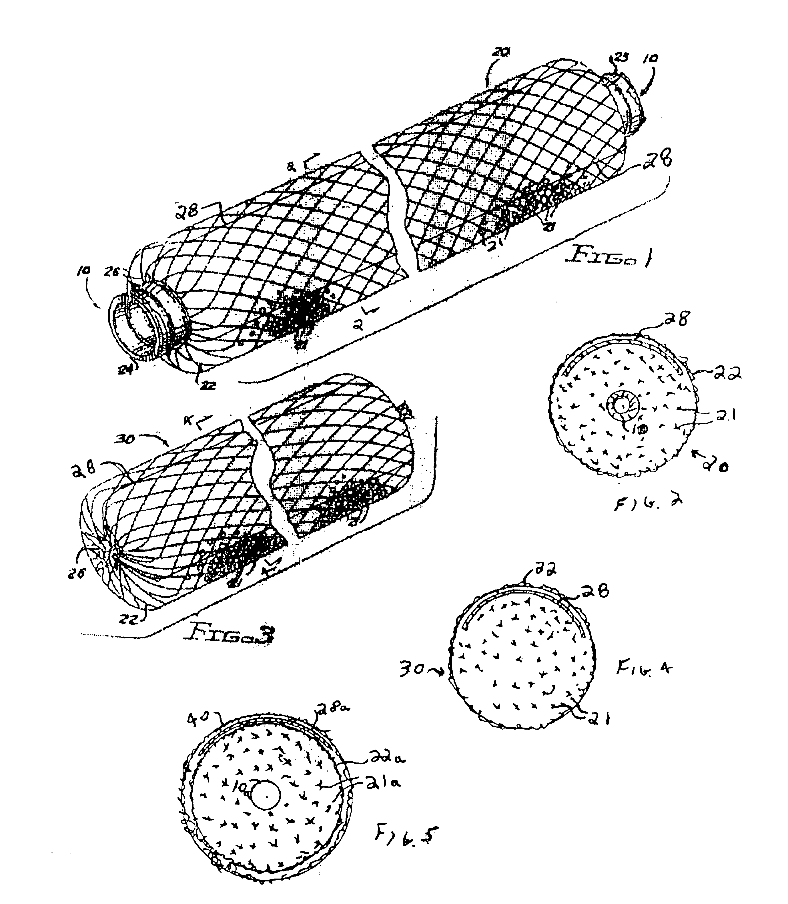
Referring now to the drawings, the longitudinally extending, flexible preassembled drainage line unit 20 illustrated in FIG. 1 includes a corrugated VC (polyvinyl chloride) perforated vent pipe 10 encased by an outer perforated sleeve member 22 of tubular nylon netting or mesh which is filled with an aggregation of discrete water impervious crush resistant lightweight plastic elements 21 and is secured to the pipe ends 24 and 25 by means of suitable conventional wires or tie fasteners 26 which prevent the escape of the loose aggregates 21.

Unit 20 as described thus far corresponds to the drainage unit illustrated in FIG. 2 in U.S. Pat. No. 5,015,123 and the detailed description set forth therein is incorporated herein by reference.

As mentioned hereinabove, in some applications employing the flexible drainage line units illustrated in the '123 patent, outside media solids such as sand, dirt or local soil placed on top of the units can penetrate into the units and thereby reduce the vo...


PUM


Abstract

A pre-assembled drainage line unit includes a flexible longitudinally extending perforated sleeve member and a loose aggregation of lightweight elements contained within the sleeve member. A pliable, water permeable barrier material extends along the sleeve member and overlies at least a portion of the aggregation to prevent the passage of solid materials, such as sand and dirt, into the aggregation.

Description

BACKGROUND OF THE INVENTIONThis invention relates generally to liquid drainage systems used on site for footings, open trenches, or nitrification fields used as discharge points for septic tanks, and more particularly to a novel flexible preassembled drainage line unit which is an improvement over the flexible preassembled drainage line units illustrated in FIGS. 2 and 3 of U.S. Pat. No. 5,015,123 (the “'123 patent”, owned by the assignee of this invention), the disclosure of which is incorporated herein by reference in its entirety.The preassembled drainage line unit illustrated in FIG. 2 of the '123 patent constitutes loose aggregate in the form of lightweight materials such as polystyrene beads provided in surrounding relationship to a perforated conduit and bound thereto by a perforated sleeve member such as plastic netting. These units, used in combination with preassembled units illustrated in FIG. 3 of the '123 patent which do not include the perforated pipe, provide a storag...

Claims


Application Information

Patent Timeline
IPC IPC(8): E03F1/00E02B11/00
CPCE03F1/002E02B11/005
Inventor RING, CARL D.
Owner EZFLOW
Learn More