Compounder-type injection molding machine

a compounder-type injection molding machine technology, applied in the direction of manufacturing tools, auxillary shaping apparatus, applications, etc., can solve the problems of adverse effects on melt quality, inability to maintain a constant melt quality, and inability to directly affect the material being ultimately produced, so as to achieve the effect of ensuring melt quality

Inactive Publication Date: 2005-02-15
KRAUSSMAFFEI TECH GMBH
View PDF12 Cites 10 Cited by
  • Summary
  • Abstract
  • Description
  • Claims
  • Application Information

AI Technical Summary

Benefits of technology

The present invention resolves prior art problems by ascertaining the melt pressure in or downstream of the extruder and to provide measures to adjust the melt pressure to a predetermined desired pressure level. By adjusting the melt pressure in this way, the melt quality can be ensured in a superior manner. In one embodiment, the melt pressure is kept constant to a desired level by moving the injection ram of the injection device backwards as melt is introduced during the filling phase of the injection cylinder of the injection device. The retraction of the injection ram is hereby active and controlled through provision of a pressure sensor which outputs a signal indicating a melt pressure state, to a control unit which uses the melt pressure state as controlled variable to move the injection ram backwards in a desired manner to thereby adjust the actual pressure value to the desired pressure level.

Problems solved by technology

A problem experienced in conventional compounder-type injection molding machines is the combination of a continuously operating extruder with an intermittently operating injection device.
However, for a number of reasons, the various proposals are endowed with drawbacks and shortcomings.
One problem of conventional injection molding machines is the absence of a constant melt quality which directly affects the material being ultimately produced.
The melt quality may be adversely affected as a result of pressure fluctuations in the extruder or downstream of the extruder.
These types of measurements are, however, inaccurate.

Method used


Image

  • Compounder-type injection molding machine
  • Compounder-type injection molding machine
  • Compounder-type injection molding machine

Examples


Embodiment Construction

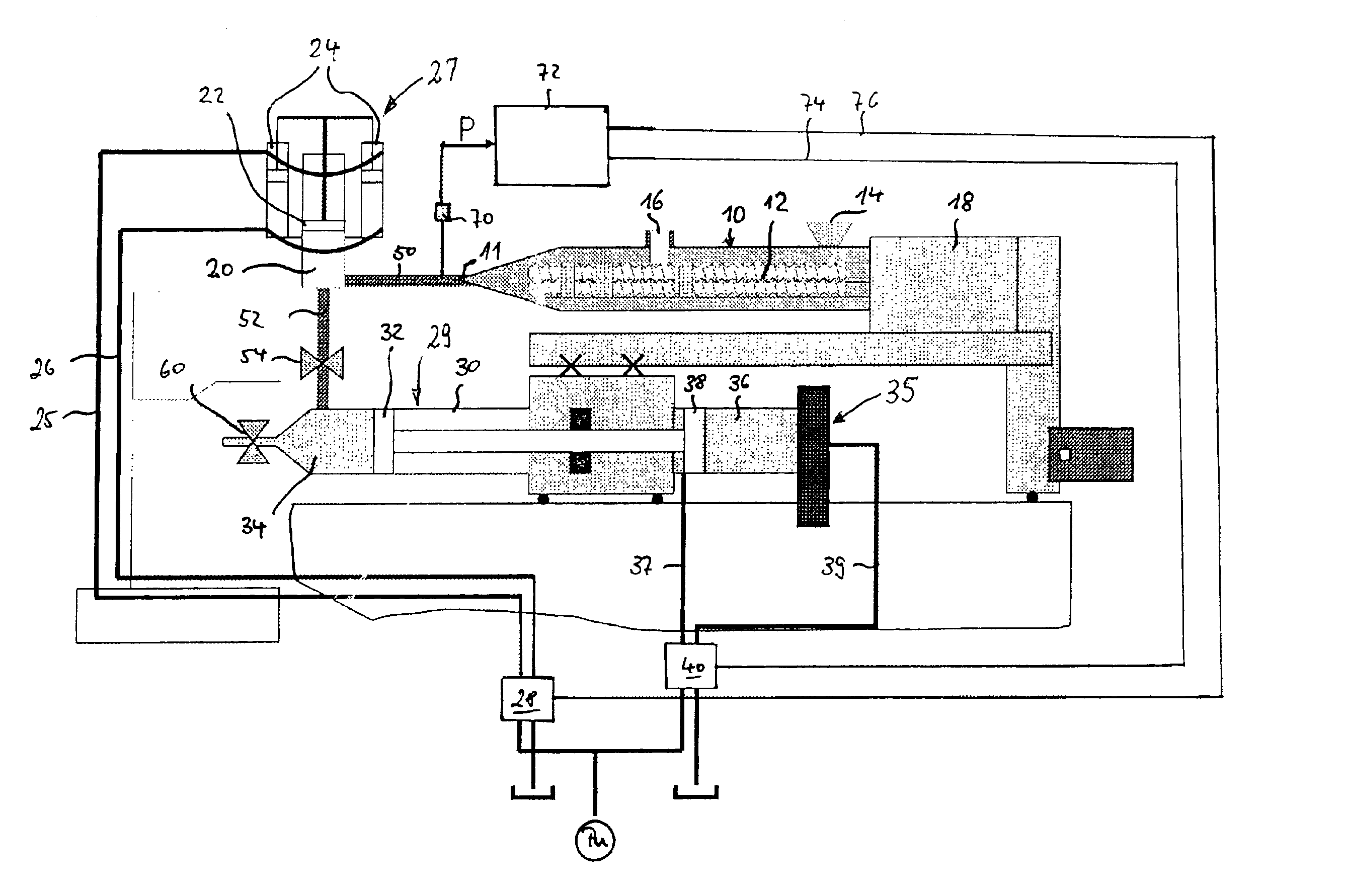
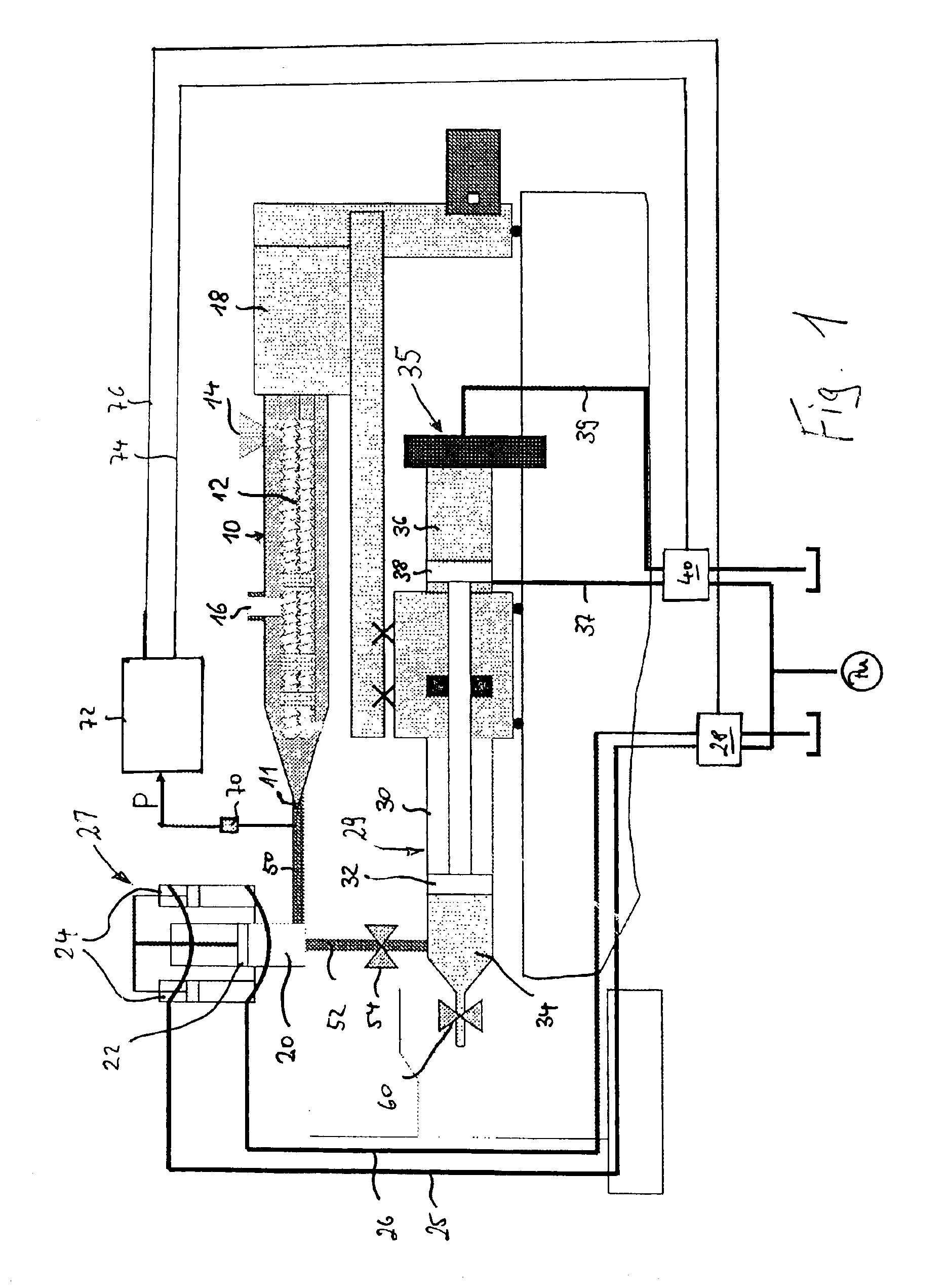
Turning now to the drawing, and in particular to FIG. 1, there is shown a greatly schematic illustration of a compounder-type injection molding machine according to the present invention including a twin screw extruder generally designated by reference numeral 10 and having two screws 12 which rotate in a same direction through operation of a drive 18. The extruder 10 may be of any commercially available construction and is shown here by way of example only. Of course, It is to be understood that the principles described in the following description with respect to twin screw extruder 10 are generally applicable to other types of extruders as well, e.g. single screw extruder or twin screw extruder with screws rotating in opposite direction.

Various materials can be introduced into the extruder 10 via a feed opening 14 and a feed opening 16. For example, plastic granulates can be supplied through the feed opening 14 whereas fibers can be supplied into the extruder 10 via feed opening ...


PUM

PropertyMeasurementUnit
melt pressure stateaaaaaaaaaa
melt pressureaaaaaaaaaa
meltaaaaaaaaaa

Abstract

In a compounder-type injection molding machine having an extruder for continuously producing a melt and at least one injection device is fluidly connected to the extruder to receive melt, a reservoir is provided which is in fluid communication with the extruder as well as with the injection device for temporary storage of melt. In order to maintain a pressure at a desired level at the outlet of the extruder, a pressure sensor is provided for ascertaining a melt pressure state downstream of an outlet of the extruder. The pressure sensor outputs a signal, commensurate with the melt pressure state, to a control unit for activating a drive in the reservoir or a drive in the injection device in response to the signal according a predetermined algorithm.

Description

CROSS-REFERENCES TO RELATED APPLICATIONSThis application claims the priority of German Patent Application, Serial No. 101 52 244.4, filed Oct. 23, 2001, pursuant to 35 U.S.C. 119(a)-(d), the disclosure of which is incorporated herein by reference.BACKGROUND OF THE INVENTIONThe present invention relates, in general, to a compounder-type injection molding machine for mixing and then injecting materials into an injection mold.Compounder-type injection molding machines of a type involved here are known for example from German Pat. No. DE 11 42 229, International Pat. Publication WO92 / 00838 or Japanese Pat. No. JP-Y36-19372. Common to all these prior art injection molding machines is the provision of a continuously operating extruder which is charged with initial plastic material, e.g., plastic granulate, to produce a plastic melt. The extruder may be configured in many different ways, e.g., as single screw extruder or twin screw extruder with screws rotating in a same direction or in op...

Claims


Application Information

Patent Timeline
Patent Type & Authority Patents(United States)
IPC IPC(8): B29C45/54B29C45/53B29C45/77
CPCB29C45/54B29C45/542B29C2045/547B29C2045/466B29C45/77B29B7/483B29B7/603B29B7/726B29B7/90
Inventor ZIMMET, RAINERZWIESELE, JOCHENSTEINHERR, THOMAS
Owner KRAUSSMAFFEI TECH GMBH
Why Eureka
Try Eureka