
Carrier head with a modified flexible membrane

a carrier head and flexible membrane technology, applied in the direction of grinding drives, manufacturing tools, lapping machines, etc., can solve the problems of non-uniform substrate thickness, non-uniform polishing, and non-planar surface, so as to reduce the deformation of the substrate, reduce the deformation, and increase the substrate cleanliness

Inactive Publication Date: 2005-02-15
APPLIED MATERIALS INC
View PDF39 Cites 29 Cited by
  • Summary
  • Abstract
  • Description
  • Claims
  • Application Information

AI Technical Summary

Benefits of technology

Potential advantages of the invention include one or more of the following. Compaction of slurry on the substrate bevel can be reduced, thereby permitting a cleaning system (such as a brush scrubber) to more thoroughly remove the slurry from the substrate and increasing substrate cleanliness. In addition, substrate deformation, such as bowing, can be reduced, thereby improving polishing uniformity.

Problems solved by technology

This nonplanar surface can present problems in the photolithographic steps of the integrated circuit fabrication process.
A reoccurring problem in CMP is non-uniform polishing, i.e., variation in the polishing rate across the substrate surface, resulting in non-uniform substrate thickness.
One cause of non-uniform polishing is substrate deformation, e.g., bowing of the substrate.
Another problem with CMP is that it is a “dirty” process.

Method used


Image

  • Carrier head with a modified flexible membrane
  • Carrier head with a modified flexible membrane
  • Carrier head with a modified flexible membrane

Examples


Embodiment Construction

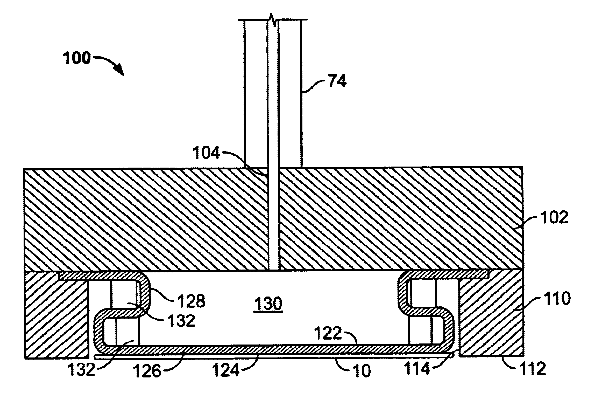
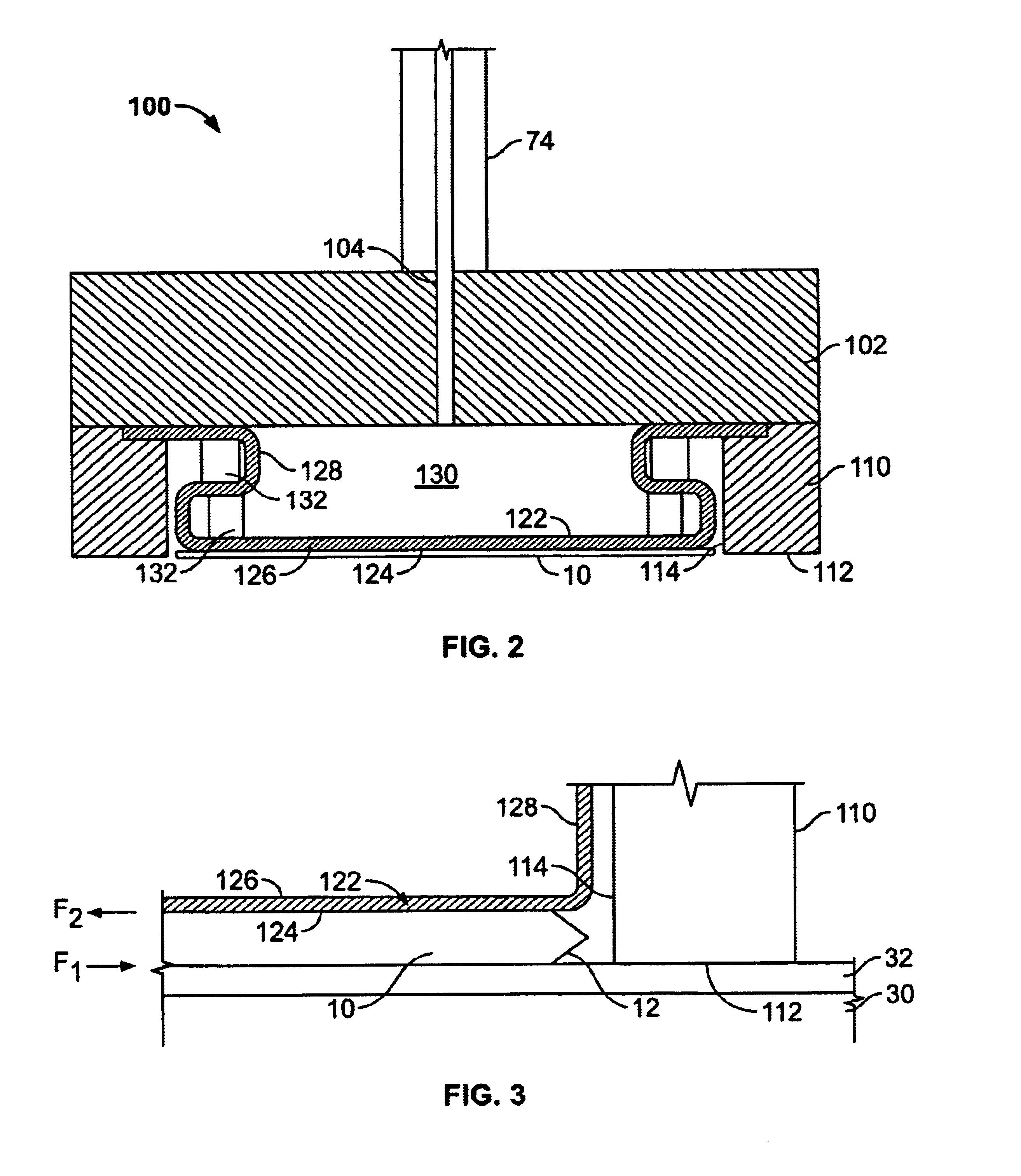
As previously noted, it is desirable to achieve a uniform polishing rate across the substrate surface during chemical mechanical polishing and to thoroughly remove slurry from substrate after polishing. It may be possible to achieve these goals by providing a substrate-holding membrane in the carrier head with a roughened surface. The roughened surface can increase the frictional force between the membrane and the backside of the substrate, so that the substrate does not move or rotate relative to the membrane. This can prevent or reduce contact between the substrate the retaining ring, thereby reducing compaction of slurry on the substrate bevel and reducing substrate deformation.

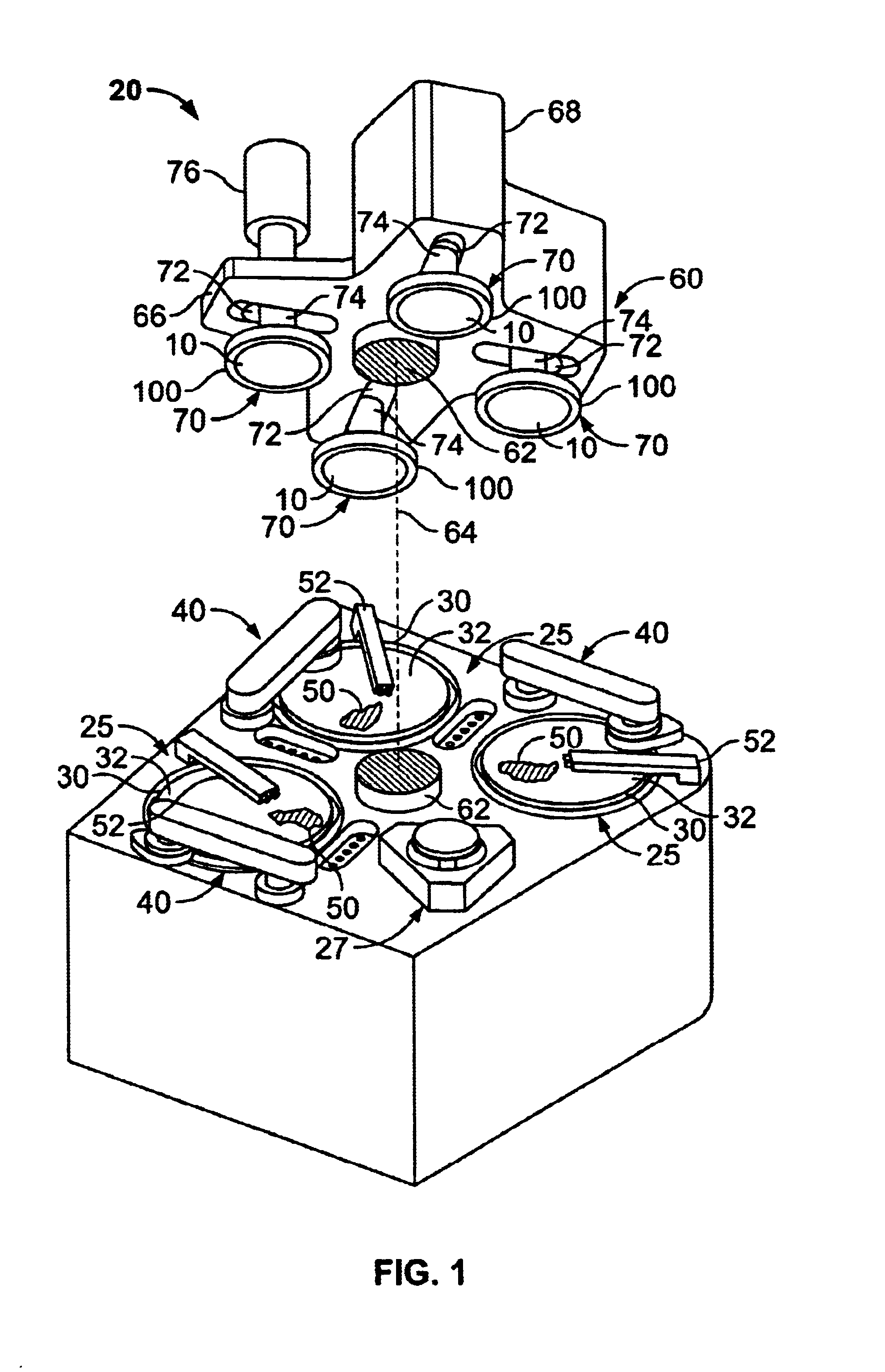
Referring to FIG. 1, one or more substrates 10 will be polished by a chemical mechanical polishing (CMP) apparatus 20. A description of a similar CMP apparatus may be found in U.S. Pat. No. 5,738,574, the entire disclosure of which is incorporated herein by reference.

The CMP apparatus 20 includes a series ...


PUM


Abstract

A carrier head for a chemical mechanical polishing apparatus includes a flexible membrane that applies a load to a substrate and a retaining ring. The friction coefficient of the lower surface of the flexible membrane is increased to prevent contact between the substrate and the retaining ring, thereby preventing slurry compaction and buildup and substrate deformation caused by such contact.

Description

BACKGROUNDThis invention relates to chemical mechanical polishing, and more particularly to a carrier head for chemical mechanical polishing.Integrated circuits are typically formed on substrates, particularly silicon wafers, by the sequential deposition of conductive, semiconductive or insulative layers. After each layer is deposited, it is etched to create circuitry features. As a series of layers are sequentially deposited and etched, the outer or uppermost surface of the substrate, i.e., the exposed surface of the substrate, becomes increasingly nonplanar. This nonplanar surface can present problems in the photolithographic steps of the integrated circuit fabrication process. Therefore, there is a need to periodically planarize the substrate surface. In addition, planarization is needed when polishing back a filler layer, e.g., when filling trenches in a dielectric layer with metal.Chemical mechanical polishing (CMP) is one accepted method of planarization. This planarization me...

Claims


Application Information

Patent Timeline
IPC IPC(8): B24B37/04B24B41/06B24B37/30B24B37/32H01L21/304
CPCB24B37/32B24B37/30
Inventor TANG, JIANSHEBROWN, BRIAN J.GARRETSON, CHARLES C.BONNER, BENJAMIN A.OSTERHELD, THOMAS H.REDEKER, FRED C.
Owner APPLIED MATERIALS INC
Learn More