Method and apparatus for converting dissipated heat to work energy

a technology of work energy and heat dissipation, which is applied in the direction of electrical apparatus casings/cabinets/drawers, instruments, and semiconductor/solid-state device details, etc., can solve the problems of consuming electrical power, requiring maintenance, and adding components to the system

Inactive Publication Date: 2005-02-15
SONY CORP +1
View PDF115 Cites 55 Cited by
  • Summary
  • Abstract
  • Description
  • Claims
  • Application Information

AI Technical Summary

Benefits of technology

It is an advantage of the present invention to transfer heat emitted from the electrical component through a heat exchanger to a heat reservoir without requiring additional energy.
to transfer heat emitted from the electrical component through a heat exchanger to a heat reservoir without requiring additional energy.
It is still further an advantage of the present invention to generate electricity from heat dissipated from the electrical component without requiring additional energy.
It is still further an advantage of the present invention to thermally induce a convective flow of an fluid through a magnetic field to create electricity which can be delivered to an external electrical storage.
It is further an advantage of the present invention to provide a method of generating energy from heat dissipated from an electrical component without requiring additional energy.
It is still further an advantage of the present invention to provide a method of transferring heat from the electrical component through a heat exchanger to a heat reservoir without requiring additional energy.

Problems solved by technology

This prior art contains deficiencies, though.
This additional pump not only adds components to the system and requires maintenance; but also, consumes electrical power.
Thus, the '410 patent has to pay an electrical energy penalty for the required pumping.
Further, the pump adds vibrational and acoustical interference to the system.
Further, slightly larger equipment, such as refrigerators, washers, dryers and other similar appliances also may generate heat in this low temperature range.
For instance, a typical CPU operating in a personal computer may operate at a maximum temperature of 70° C. without experiencing a thermal failure; but due to the heat generated by a typical CPU, however, the temperature often reaches 100° C. and above which could lead to thermal failure.

Method used


Image

  • Method and apparatus for converting dissipated heat to work energy
  • Method and apparatus for converting dissipated heat to work energy
  • Method and apparatus for converting dissipated heat to work energy

Examples


Embodiment Construction

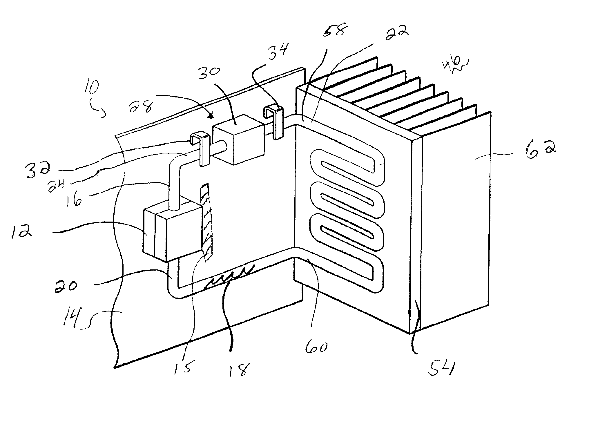
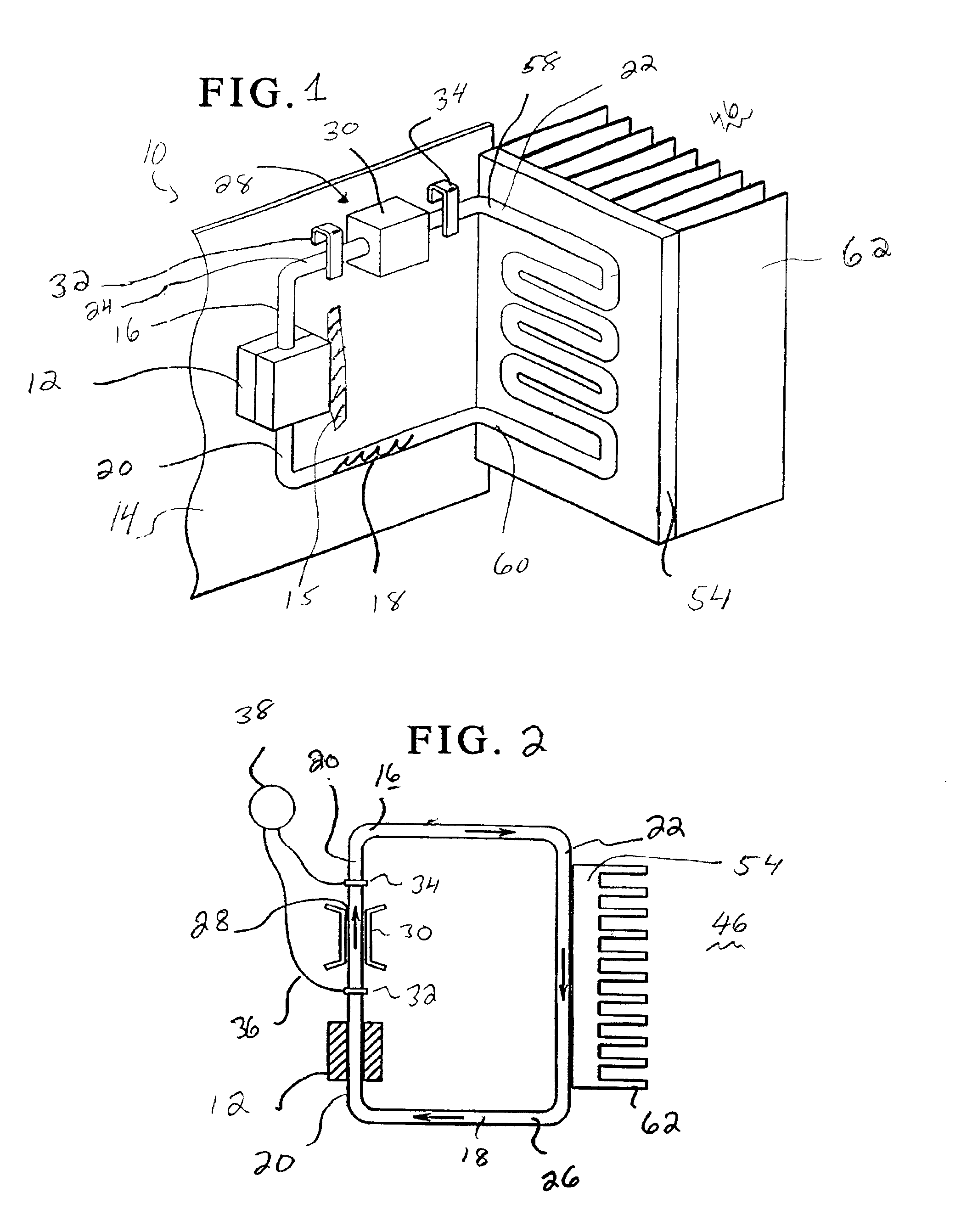
As discussed above, there is provided an apparatus and method for efficiently transferring unconverted or remaining waste heat away from a heat source, such as an electrical component, and for converting waste heat from the heat source into other forms of energy such as work energy.

The present invention is directed to converting waste heat for energy conversion in a 75° C.-150° C. temperature range into other useful energy. As mentioned above and described more fully below, in accordance with principles of the invention, power is derived from waste heat via an energy converter producing approximately 1W-10W yet only occupying several cm3 of volume. Thus, the present invention can generate power derived from the waste heat for output for operating other devices for cooling purposes (such as a fan or a miniature refrigerator), extending battery life, re-charging depleted batteries, and reducing the electricity demand on the power grid in the office or home.

FIG. 1 illustrates in perspe...


PUM


Abstract

A method for converting lower temperature dissipated heat to other useful energy and apparatus therefore. Heat energy is transferred to a fluid contained within a conduit, and natural convection of the fluid is utilized to transfer kinetic energy of the heat to another type of energy such as electrical energy.

Description

BACKGROUND OF THE INVENTIONThe present invention generally relates to methods and apparatuses for dissipating heat away from devices generating heat. In addition, the invention relates to methods and other apparatuses for converting heat energy into other forms of energy.The research and development of liquid metal magneto hydro dynamic energy conversion systems is gaining increasing attention in their various proposed modes, consisting of single-phase or two-phase fluid flow for a wide range of heat sources, e.g., solar energy, waste heat, nuclear energy, etc. Since the thermodynamic “availability,” or energy content, of a solid or fluid increases strongly with absolute temperature, efficient electric power generation from a heat source is usually performed at elevated temperatures, often in the range of 600° C.-800° C. In the categories of high temperature conversion, the systems are generally large, with each generator unit producing megawatts of electric power and occupying a vo...

Claims


Application Information

Patent Timeline
Patent Type & Authority Patents(United States)
IPC IPC(8): F03G7/00F28D15/00H01L23/427H01L23/34F28D15/02H01L23/473H02K44/08H05K7/20
CPCF03G7/00F28D15/00F28D15/0266F28F23/00H01L23/4275H01L2924/0002F28F2250/08H01L2924/00
Inventor YAZAWA, KAZUAKIBAR-COHEN, AVRAM
Owner SONY CORP
Why Eureka
Try Eureka