Electromotive devices using notched ribbon windings

a technology of notched ribbon and electric motor, which is applied in the direction of windings, stator/rotor bodies, and applying solid insulation, etc., can solve the problems of counter-intuitive use of notched ribbon in the cross-over area, and achieve the effect of reducing electrical resistance, increasing copper fraction, and reducing electrical resistan

Inactive Publication Date: 2005-02-15
MAGNETIC POWER MOTION
View PDF15 Cites 24 Cited by
  • Summary
  • Abstract
  • Description
  • Claims
  • Application Information

AI Technical Summary

Benefits of technology

The present invention provides for electromotive device designs incorporating multiple phase windings, each winding including one or more notched ribbon conductors, which results in higher power density devices than those available in the prior art. The designs improve the performance of the parameters affecting the electromagnetic force generated by the device, especially the armature surface current density “K”, and to some extent the airgap surface area S.
The multiple phase windings of the present invention utilize ribbon conductors with notches in the phase cross-over areas instead of using wire conductors. This results in many advantages, including:Lower electrical resistance: A ribbon winding has a higher copper fraction (i.e. % of copper, as opposed to insulation and air, which fills a slot area), with fractions of 90% or more possible in contrast to copper fractions in the 60% range for round wire windings. The windings of the present invention have notched cross-over areas (areas where one phase winding crosses over another phase winding), and these notches increase the resistance to the flow of electricity. Thus, it is counter-intuitive to use notches in the cross-over areas. However, the use of these notches, as compared to bending of the windings past each other, results in a substantial reduction in the required length of the end-turns of the windings, and this reduction in end-turn length more than compensates for the increase in electrical resistance due to the notches. Note that the end-turn areas are typically, but not necessarily, non-work-producing areas of the windings, so reducing the length of these end-turns areas improves performance of the device by reducing the overall thermal and electrical resistances and by allowing a smaller device for a higher power density.Lower thermal resistance: Thermal resistance is a property relating the temperature rise in the winding to its heat conduction (or heat flow). It is a measure of how difficult it is for heat to flow out of the winding. With single stator, dual rotor, axial gap PMM's, heat generated by the windings primarily flows out through the exterior end-turn / housing interface. The high copper fraction of the ribbon windings of the present invention (almost equivalent to solid copper) allows heat to flow easily along the length of the winding to the end-turns, which are clamped to the PMM's housing, which acts as a heat sink to cool the windings. Furthermore, the notched cross-over areas allow both axially oriented faces of the end-turns to contact the housing in the “bridging” length of the end-turns, thereby increasing the thermal contact area for more effective cooling, since both end-turn faces are available for heat transfer.Greater Magnetic Airgap area: The use of notches resulting in planar stator faces often allows the magnetic airgap surface area S to be increased by extending partially over the end turn areas, where the conductors are transitioning from radial to tangential orientations, but still have a significant radial component which can contribute to torque production.More Compact Structure: The use of notches allows the radial height of the end-turns (as well as lengths) to be shorter for a more compact winding structure. This, in turn, allows smaller machines with greater power density to be constructed.
Another benefit of this PMM design is that the actuator housing can be totally enclosed with minimal impact of cooling performance (since cooling primarily occurs by end-turn conduction, not internal convection of the windings).

Problems solved by technology

Thus, it is counter-intuitive to use notches in the cross-over areas.

Method used


Image

  • Electromotive devices using notched ribbon windings
  • Electromotive devices using notched ribbon windings
  • Electromotive devices using notched ribbon windings

Examples


Embodiment Construction

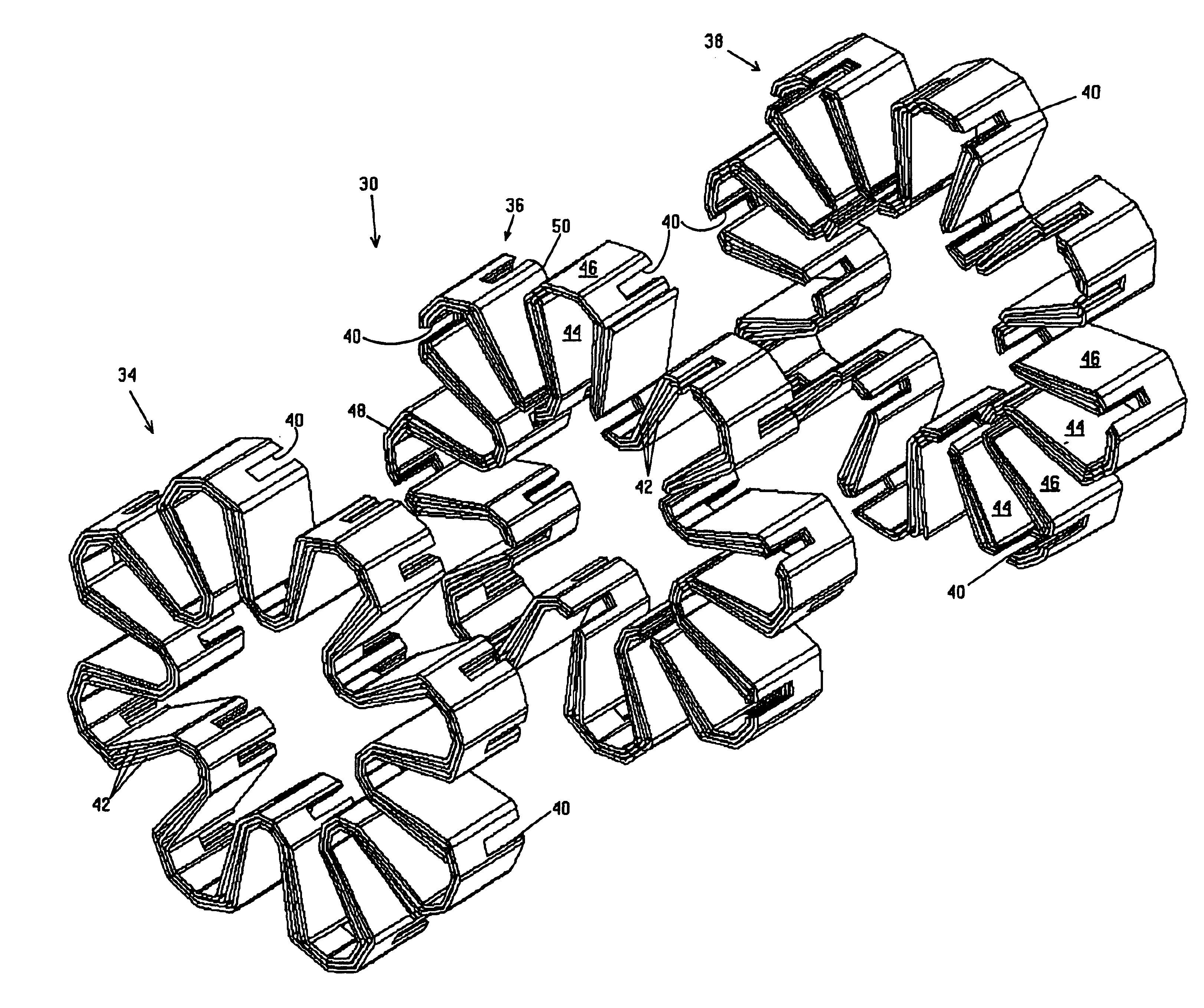
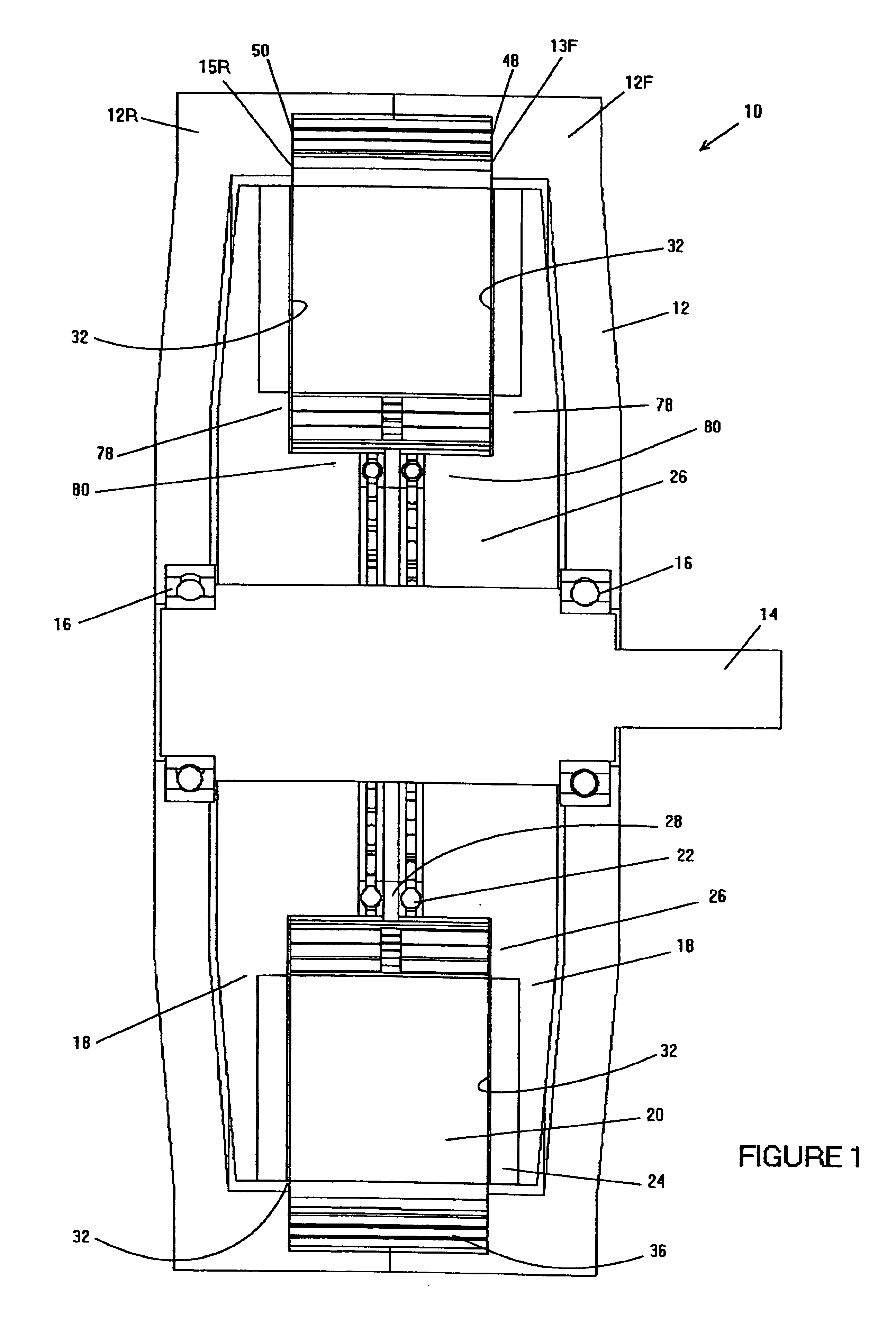
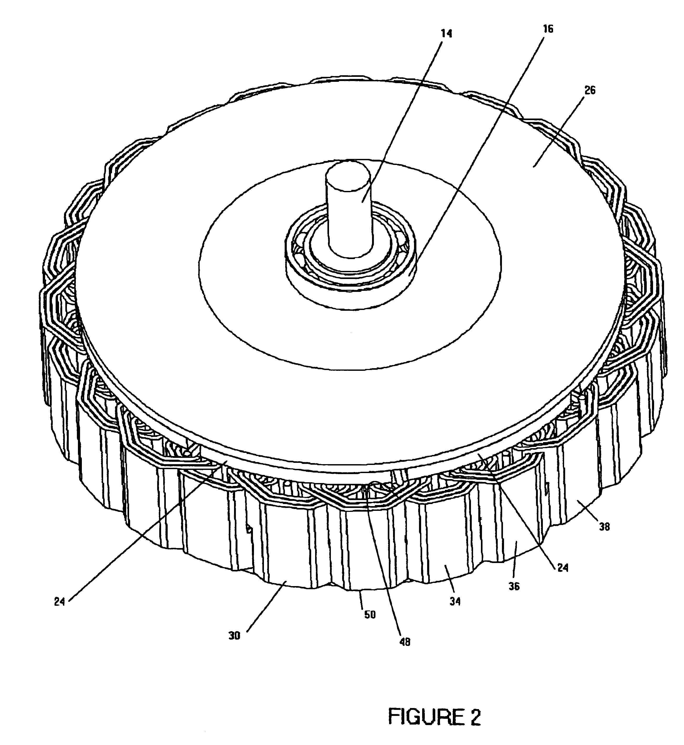
FIG. 1 is a sectional view (cross-hatching not shown for clarity) of an embodiment of a permanent magnet synchronous machine (PMM) 10 made in accordance with the present invention. The PMM 10 includes a housing 12, which is made up of a front housing portion 12F and a rear housing portion 12R. It also includes a shaft 14, which is supported for rotation by radial bearings 16, one or more rotor disks 18 (also referred to as rotors 18), which rotate with the shaft 14, one or more stators 20 which are secured, as by clamping, to the housing 12, and a plurality of thrust bearings 22. As will be explained later in more detail, the front housing portion 12F has a front flange portion 13F, and the rear housing portion 12R has an opposed, rear flange portion 15R. The front and rear axial faces 48, 50 of the exterior end-turn portions 64 (See FIG. 20) of the stator 20 are clamped between these opposed front and rear flanges 13F, 15R.

Referring to FIGS. 1, 2, and 3, each of the rotors 18 inclu...


PUM

PropertyMeasurementUnit
heightaaaaaaaaaa
thicknessaaaaaaaaaa
shapeaaaaaaaaaa

Abstract

A multiple phase winding for an electromotive device comprised of individual phase windings. Each phase winding includes multiple layers of conductors and defines working length portions and interior and exterior end-turn portions, wherein at least one set of end-turn portions defines notches which cut across the height dimension of all the layers of conductors. The notches of different phases intermesh. This geometry promotes low electrical resistance within the phase windings and good conductive heat transfer between the multiple phase winding and the housing of the electromotive device, allowing higher power density from the device.

Description

BACKGROUND OF THE INVENTIONThe present invention relates to electromotive devices including electromagnetically excited machines and permanent magnet synchronous machines (PMM's). For clarity and simplicity, the term permanent magnet synchronous machine (PMM) is used throughout this specification, but it should be clearly understood that the term is intended to include electromotive devices in general, including electromagnetically excited machines.The electromagnetic forces developed in a PMM result from the interaction of a permanent magnet field with a stator current. This interaction can be fundamentally represented by the relation:F=k*B*K*S Where:F is the electromagnetic forcek is a proportionality constant depending on geometry,B is the airgap flux density,K is the armature surface current density, andS is the airgap surface area.In order to increase the power density of the PMM, it is necessary to increase the airgap flux density B or the armature surface current density K, o...

Claims


Application Information

Patent Timeline
Patent Type & Authority Patents(United States)
IPC IPC(8): H02K41/03H02K21/12H02K21/24H02K15/04H02K3/04
CPCH02K3/04H02K15/0478H02K41/03H02K21/24Y10T29/49009Y10T29/49012
Inventor KELECY, PATRICKRECEVEUR, PAUL
Owner MAGNETIC POWER MOTION
Why Eureka
Try Eureka