Method and apparatus for magnetic focusing of off-axis electron beam

a technology of magnetic focusing and electron beam, which is applied in the direction of discharge tube/lamp details, instruments, heat measurement, etc., can solve the problems of essentially one-dimensional problem, beams that are more susceptible to defocusing effects, and weak focusing, so as to prevent or substantially reduce beam twist

Inactive Publication Date: 2005-02-15
COMM & POWER IND
View PDF16 Cites 2 Cited by
  • Summary
  • Abstract
  • Description
  • Claims
  • Application Information

AI Technical Summary

Benefits of technology

Axially symmetric magnetic fields are provided about the longitudinal axis of each beam of a multi-beam electron beam device. The magnetic field symmetry is independent of beam voltage, beam current and applied magnetic field strength. A flux equalizer assembly is disposed between the cathodes and the anodes and near the cathodes of a multi-beam electron beam device. The assembly includes a ferromagnetic flux plate completely contained within the magnetic focusing circuit of the device. The flux plate includes apertures for each beam of the multi-beam device. A flux equalization gap or gaps are disposed in the flux plate to provide a perturbation in the magnetic field in the flux plate which counters the asymmetry induced by the off-axis position of the beam. The gaps may be implemented in a number of ways all of which have the effect of producing a locally continuously varying reluctance that locally counters the magnetic field asymmetry. The flux equalizer assembly prevents or substantially reduces beam twist and maintains all of the electron beams of the device as linear beams.

Problems solved by technology

The result is weaker focusing and a beam more susceptible to defocusing effects caused by rf-field interactions with the beam.
In such cases the beam axis and the focusing field axis can be aligned to achieve radial and azimuthal symmetry, and the design problem becomes essentially one-dimensional—only the magnitude of the axial magnetic field must be controlled.
It has long been recognized that the designers of electron devices with multiple linear beams face a difficult 3-dimensional design problem.
However, this has limited the power levels achieved.
This technique reduces, but does not entirely eliminate, the twisting of the beam.
Such devices typically have performance limitations, including device life and operating voltage limitations, that result from space restrictions caused by placing the individual beams near the longitudinal axis of the device.
These include using individual cathode coils to shape the magnetic field, an approach which can be difficult and complex to implement.
A problem with prior confined-flow multi-beam devices that employ offset pole-piece apertures to aid in focusing the beams is that the apertures, which are fixed in position, will be properly positioned for only one set of operating conditions because the amount of twist depends upon beam current and voltage and magnetic field strength.
If the device is operated outside of the specified designed-in conditions, the beam will intersect with portions of plates through which the apertures are placed at places other than the apertures resulting in damage to the device and non-optimal operation, or the beam will pass off-center through the apertures (rather than hitting the polepiece) and thereby induce further field asymmetry and therefore suffer greater beam twist.
Confined-flow multi-beam devices with beams disposed near the device axis additionally suffer from performance limitations that result from space restrictions within the device.
These limitations include shorter device life due to higher operating cathode current density, operating voltage limitations due to higher electrode voltage gradients, and mechanical and thermal design challenges imposed by the requirement to work within a restricted space.

Method used


Image

  • Method and apparatus for magnetic focusing of off-axis electron beam
  • Method and apparatus for magnetic focusing of off-axis electron beam
  • Method and apparatus for magnetic focusing of off-axis electron beam

Examples


Embodiment Construction

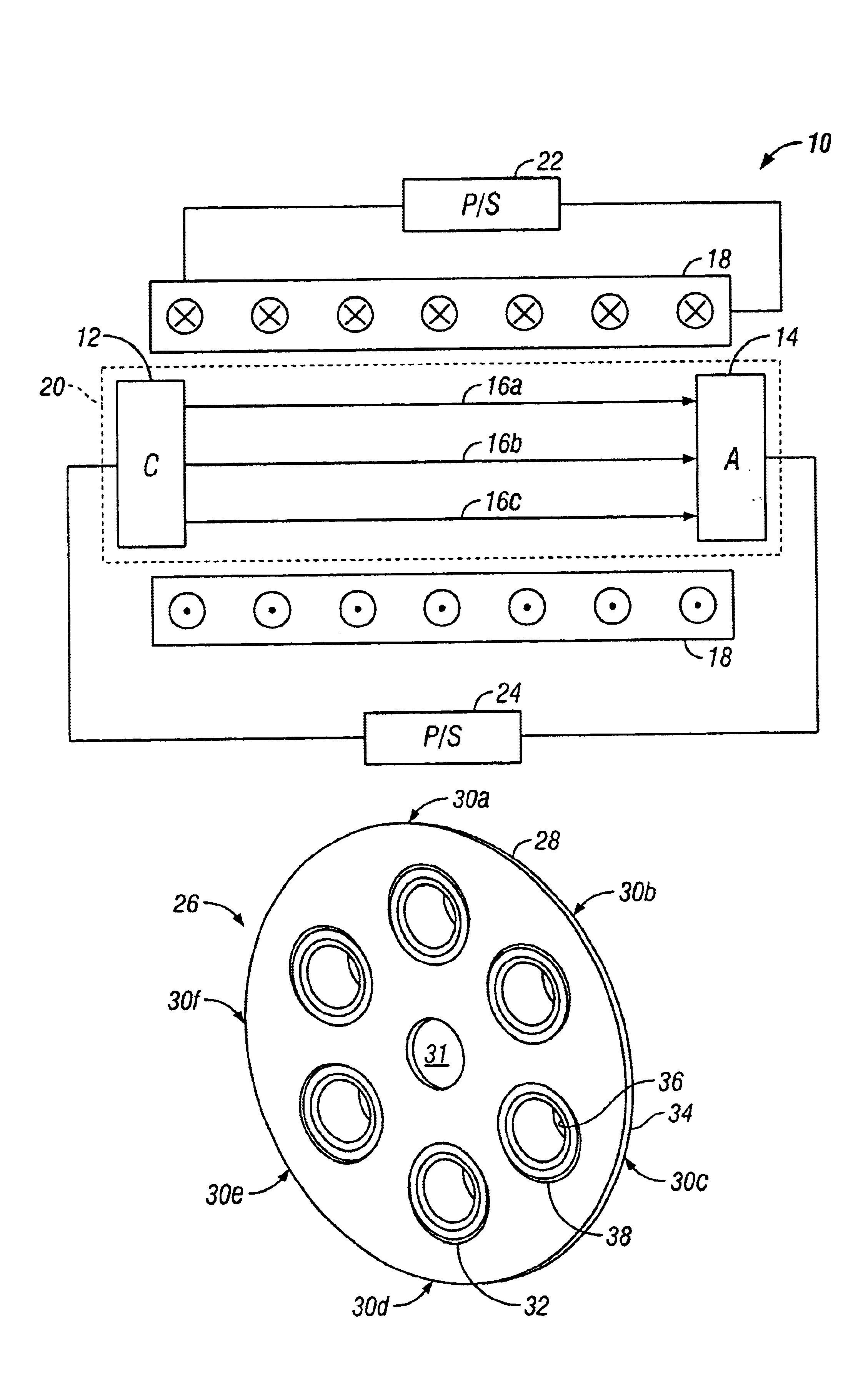
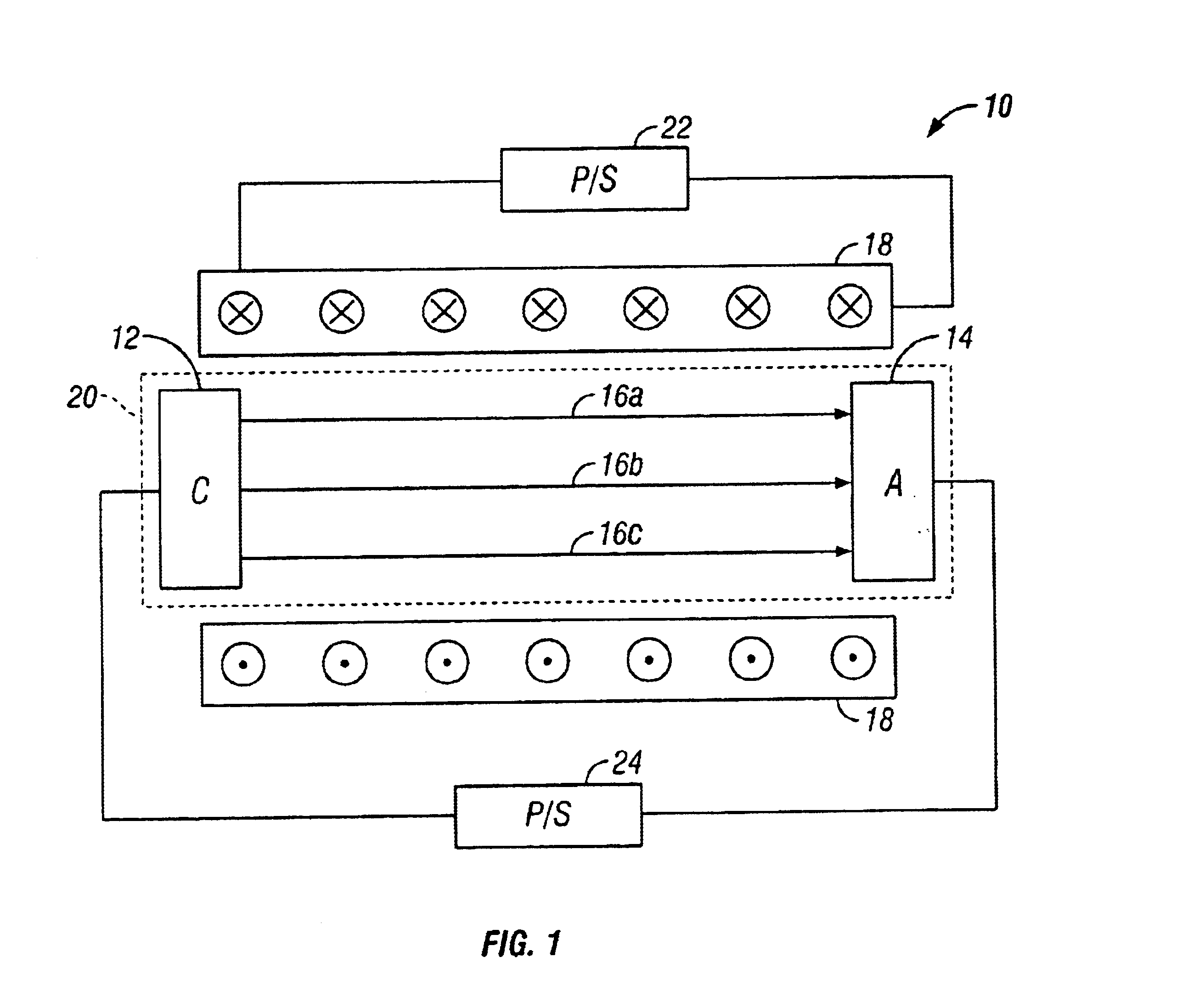
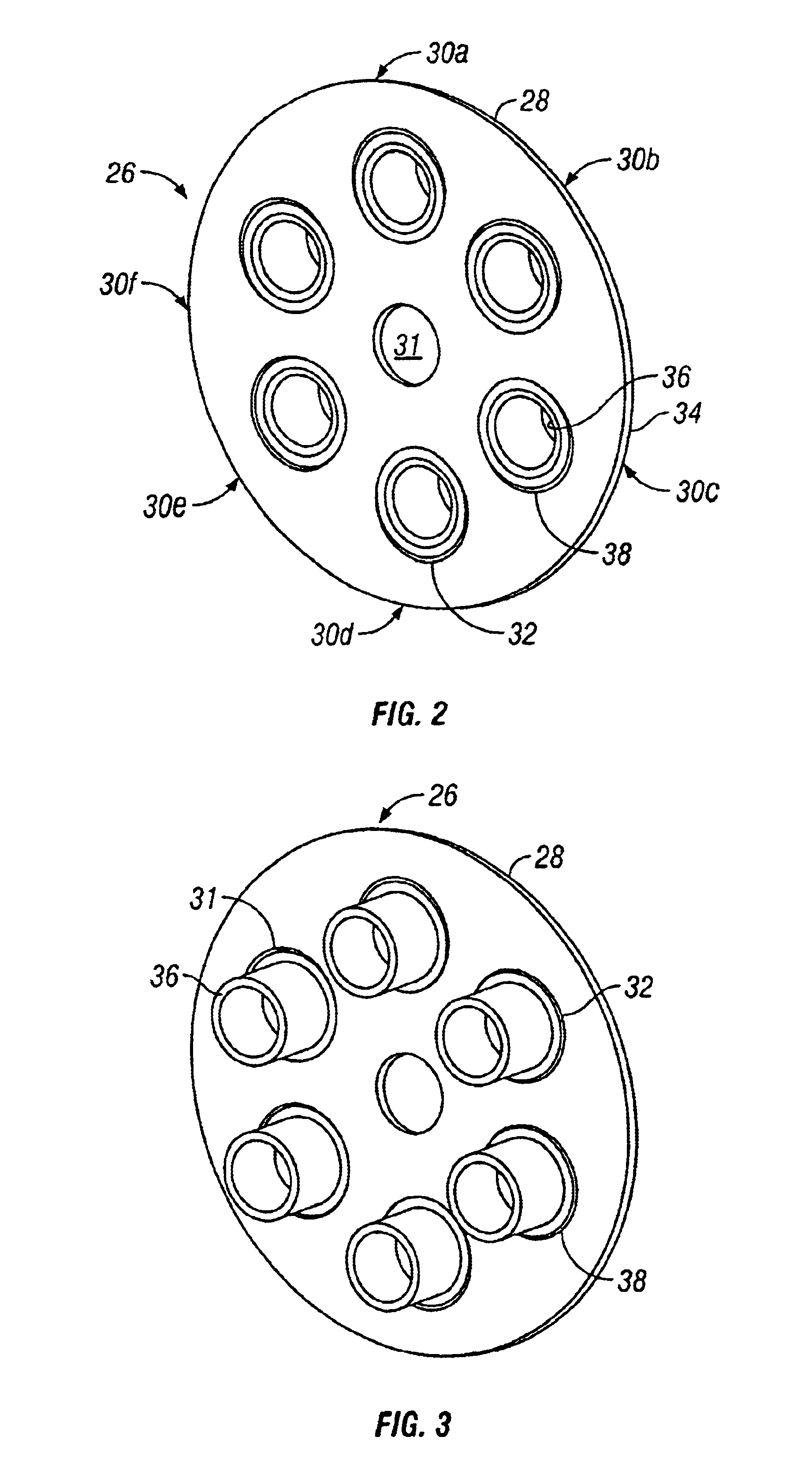
Embodiments of the present invention are described herein in the context of a method and apparatus for magnetic focusing of off-axis electron beams. The invention is intended to be useable with a broad range of multi-beam electron devices as well as single-beam linear electron devices employing an off-axis electron beam. Those of ordinary skill in the art will realize that the following detailed description of the present invention is illustrative only and is not intended to be in any way limiting. Other embodiments of the present invention will readily suggest themselves to such skilled persons having the benefit of this disclosure. Reference will now be made in detail to implementations of the present invention as illustrated in the accompanying drawings. The same reference indicators will be used throughout the drawings and the following detailed description to refer to the same or like parts.

In the interest of clarity, not all of the routine features of the implementations descr...


PUM

PropertyMeasurementUnit
magnetic fieldaaaaaaaaaa
magnetic focusingaaaaaaaaaa
magnetic field asymmetryaaaaaaaaaa

Abstract

Axially symmetric magnetic fields are provided about the longitudinal axis of each beam of a multi-beam electron beam device. The magnetic field symmetry is independent of beam voltage, beam current and applied magnetic field strength. A flux equalizer assembly is disposed between the cathodes and the anodes and near the cathodes of a multi-beam electron beam device. The assembly includes a ferromagnetic flux plate completely contained within the magnetic focusing circuit of the device. The flux plate includes apertures for each beam of the multi-beam device. A flux equalization gap or gaps are disposed in the flux plate to provide a perturbation in the magnetic field in the flux plate which counters the asymmetry induced by the off-axis position of the beam. The gaps may be implemented in a number of ways all of which have the effect of producing a locally continuously varying reluctance that locally counters the magnetic field asymmetry. The flux equalizer assembly prevents or substantially reduces beam twist and maintains all of the electron beams of the device as linear beams.

Description

FIELD OF THE INVENTIONThe present invention relates to the field of electron beam devices. More particularly, the present invention relates to the magnetic focusing of plural off-axis electron beams in a device with multiple linear beams. Such devices include, for example, microwave power amplifiers and oscillators, inductive output tubes, klystrons and the like.BACKGROUND OF THE INVENTIONIn linear beam electron tubes the source of electrons is a cathode, which, to achieve low electron emission densities, is usually larger than the desired beam diameter. Electrons emitted by the cathode are acted upon by a set of electrodes with voltages impressed thereon which causes the electrodes to accelerate and optically focus the electrons to the desired beam size. The magnetic focusing field than constrains the beam and prevents it from spreading. The magnetic focusing field can be produced either by electromagnets, permanent magnets, or a combination of the two.There are two preferred syste...

Claims


Application Information

Patent Timeline
Patent Type & Authority Patents(United States)
IPC IPC(8): G01K1/08H01J23/087H01J23/02H01J25/00H01J29/70H01J29/00H01J25/10H01J3/14H01J29/46H01J3/00H01J3/20
CPCH01J3/20H01J23/0876H01J23/087
Inventor CATTELINO, MARK J.FRIEDLANDER, FRED I.
Owner COMM & POWER IND
Why Eureka
Try Eureka