
Methods and apparatus for detecting threats in different areas

a technology of polarized reflected energy and methods, applied in the field of threat detection, can solve the problems of difficult implementation of techniques based on differences between levels of different polarized reflected energy, potential cost, and inability to know the concealed weapons or explosive detection systems available, and achieve the effect of reducing clutter on the display

Inactive Publication Date: 2005-02-15
KOSOWSKY LESTER
View PDF16 Cites 48 Cited by
  • Summary
  • Abstract
  • Description
  • Claims
  • Application Information

AI Technical Summary

Benefits of technology

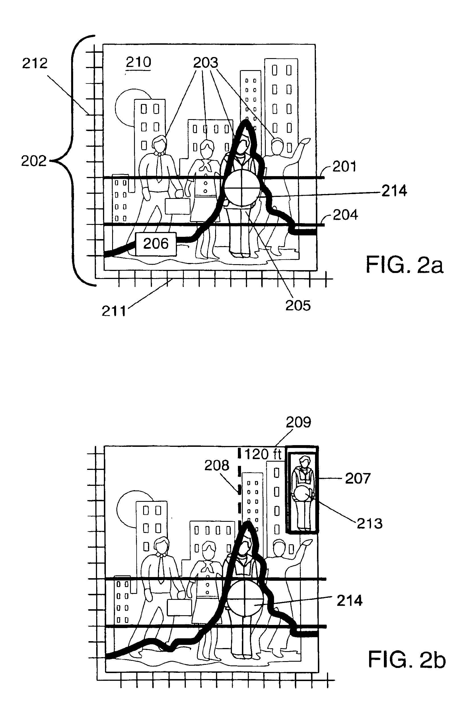
In one particular exemplary embodiment, the region to be examined is divided into segments, e.g., cells, corresponding to different physical areas. The distance of the cells from the combined receiver / transmitter unit used in various exemplary embodiments of the present invention is taken into consideration when assessing the amount of detected energy returned from signals transmitted into a particular area. In various embodiments, a threat threshold is determined as a function of a weighted average of detected energy measurements corresponding to multiple areas of a region scanned during an analysis period. In generating the weighted average, energy measurements corresponding to different areas are adjusted, e.g., normalized, as a function of distance to the area from which the signals are received and the expected decrease in power as the distance increases. The weighted energy measurements are averaged to form a value which is used in generating the threat threshold for the corresponding analysis period. The weighted energy measurement corresponding to a particular area, e.g., cell, is compared to the generated threshold and a threat is declared when the returned energy for an area exceeds the dynamically generated threshold level. The threat threshold level is normally generated to be higher than the weighted energy average, e.g., by a fixed or user adjustable amount, to reduce the risk of threats being declared erroneously.
In cases where hidden weapons on individuals is the primary concern the display may limit the visual display of information to areas, e.g., cells of a scanned region, where a human presence is detected, e.g., through the use of thermal or other information. Such an embodiment reduces clutter on the display and helps a user focus on potential threats.

Problems solved by technology

To date, there are no known concealed weapons or explosive detection systems available that purport to detect a concealed weapon (or weapons) or explosive devices from a distance of more than 20 yards.
This system has the disadvantage of relying on the presence of unique spectral signatures, which must be pre-stored or learned by a computer employing artificial intelligence techniques.
This technique which relies on differences between levels of different polarized reflected energy is difficult and potentially costly to implement.

Method used


Image

  • Methods and apparatus for detecting threats in different areas
  • Methods and apparatus for detecting threats in different areas
  • Methods and apparatus for detecting threats in different areas

Examples


Embodiment Construction

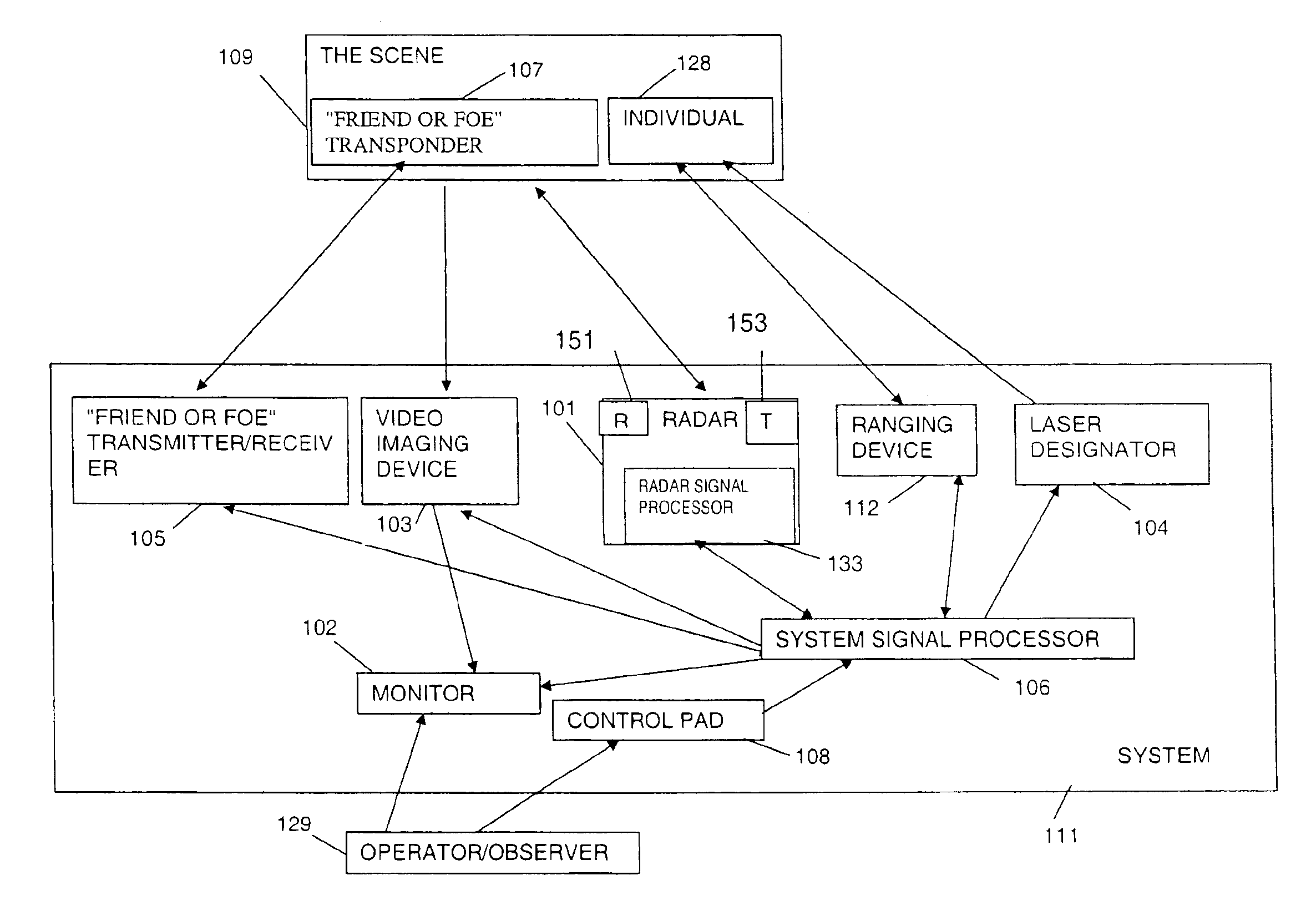
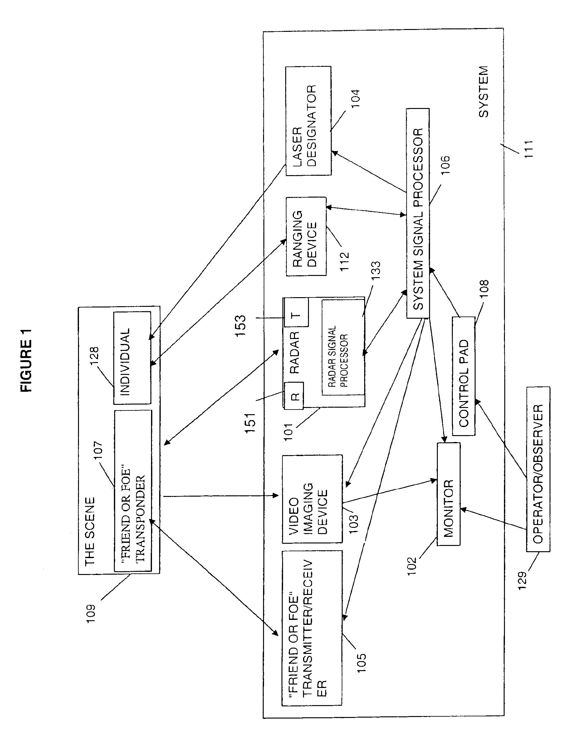
Referring to FIG. 1, the exemplary concealed weapon / explosive detection System 111 may advantageously be positioned more than 100 yards from the Scene 109 to be monitored. The system 111 includes various components 101, 102, 103, 104, 105, 106, 108, 133 coupled together to permit the communication and / or transmission of signals and / or control information between the elements as shown in FIG. 1 through the use of arrows. The Operator / Observer 129 interacts through Control Pad 108 to direct System Signal Processor (SSP) 106 to control each of the operator selectable options of the System 111. The Operator / Observer 129 observes the Scene 109 by using the Monitor 102. The Control Pad 108 allows the Operator to interact with each of the elements of the System 111 through commands to the SSP 106. System 111 can, and in various embodiments does, implement an automated scanning process, without the need for a human operator. Also, the entire System 111 can, and in various embodiments is, fi...


PUM


Abstract

Methods and apparatus for early detection and identification of a threat such as individuals carrying hidden explosive materials, land mines on roads, etc. are disclosed. Methods comprise transmitting radar signals in the direction of a potential threat, measuring the energy in reflected signals, dynamically generating a threat threshold value from signals received from multiple areas and comparing the energy in the reflected signals corresponding to different areas to the generated threat threshold value. The threat threshold value may be generated by averaging the weighted reflected energy measured from different areas during a single scan of a region including the different areas. The contribution to the threshold from different areas is weighted in some embodiments as a function of the distance from the transmitter and / or receiver to the particular area. Analysis of areas and treating different areas as segments facilitates accurate analysis and display of threat information.

Description

FIELD OF THE INVENTIONThe invention relates generally to the field of threat detection and, more specifically, to a system and method for identifying potential threats and displaying information indicating the position of the potential threats both indoors and outdoors.BACKGROUND OF THE INVENTIONThe suicide or homicide bomber has been identified as the one threat that is virtually unstoppable. The thinking of the bomber defies all societal norms. With that being said, the logical solution to the problem would be the development of a means for detecting the bomber at a safe distance from a potential target. To date, there are no known concealed weapons or explosive detection systems available that purport to detect a concealed weapon (or weapons) or explosive devices from a distance of more than 20 yards. Reference is made to an article in the July 2002 Discover Magazine entitled “Beyond X-ray Vision” by Ivan Amato for a recent survey of the current state of the technology. Attention...

Claims


Application Information

Patent Timeline
IPC IPC(8): G01S13/00F41H13/00G01S13/87G01S13/74G01S13/08
CPCF41H13/00G08B31/00G01S13/872G01S13/08G01S13/74G01S13/86
Inventor LEVITAN, ARTHUR C.KOSOWSKY, LESTER
Owner KOSOWSKY LESTER
Learn More