

Solid state scanning type optical recording device
Inactive Publication Date: 2005-02-15
MINOLTA CO LTD
View PDF11 Cites 3 Cited by
- Summary
- Abstract
- Description
- Claims
- Application Information
AI Technical Summary
Benefits of technology
An object of the present invention is to eliminate the previously mentioned disadvantages.
Another object of the present invention is to provide an electro-optic element drive device which minimizes noise generation.
Another object of the present invention is to provide a solid state scanning type optical recording device having few operation errors.
Problems solved by technology
New design and production of 8 to 12 bit driver ICs to match the increase in the number of gradients present disadvantages in terms of development time and cost.
Method used
View moreImage
Smart ImageViewing Examples

Examples
first embodiment
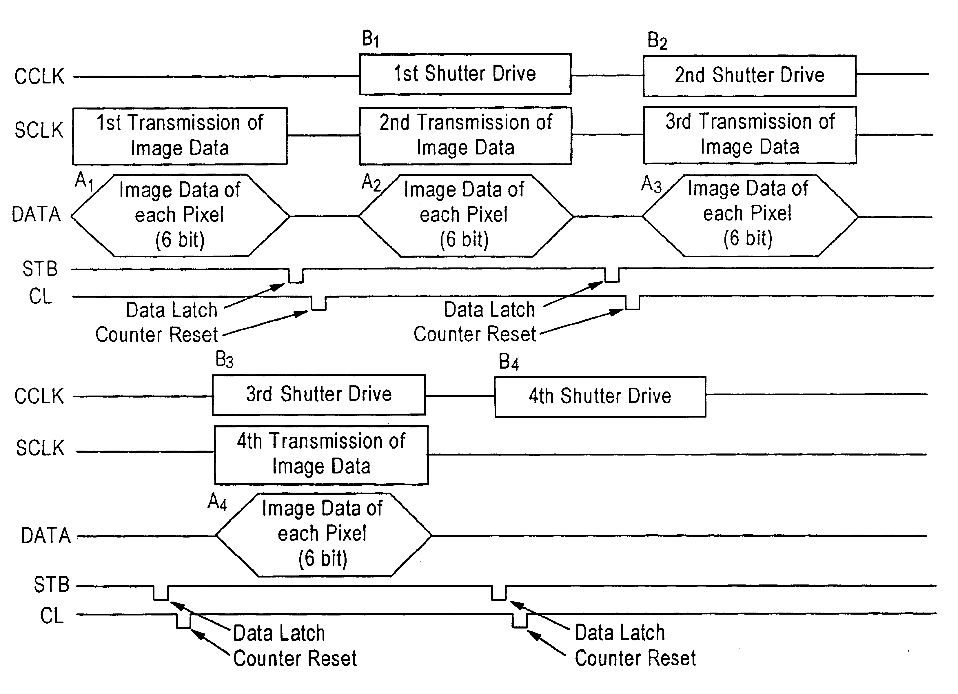
FIG. 3 is a timing chart of the driver IC of the present invention;
FIG. 4 is a timing chart of the various types of signals in a first embodiment of the present invention;
FIG. 5 is a timing chart of the various types of signals in the general-purpose mode of the first embodiment of the present invention;
second embodiment
FIG. 6 is a timing chart of the driver IC of the present invention;
FIG. 7 is a timing chart of the various types of signals in the second embodiment of the present invention;
FIG. 8 is a timing chart of the various types of signals in the general-purpose mode of the second embodiment of the present invention;
third embodiment
FIG. 9 is a timing chart of the various types of signals in the present invention;
Login to View More PUM
 Abstract
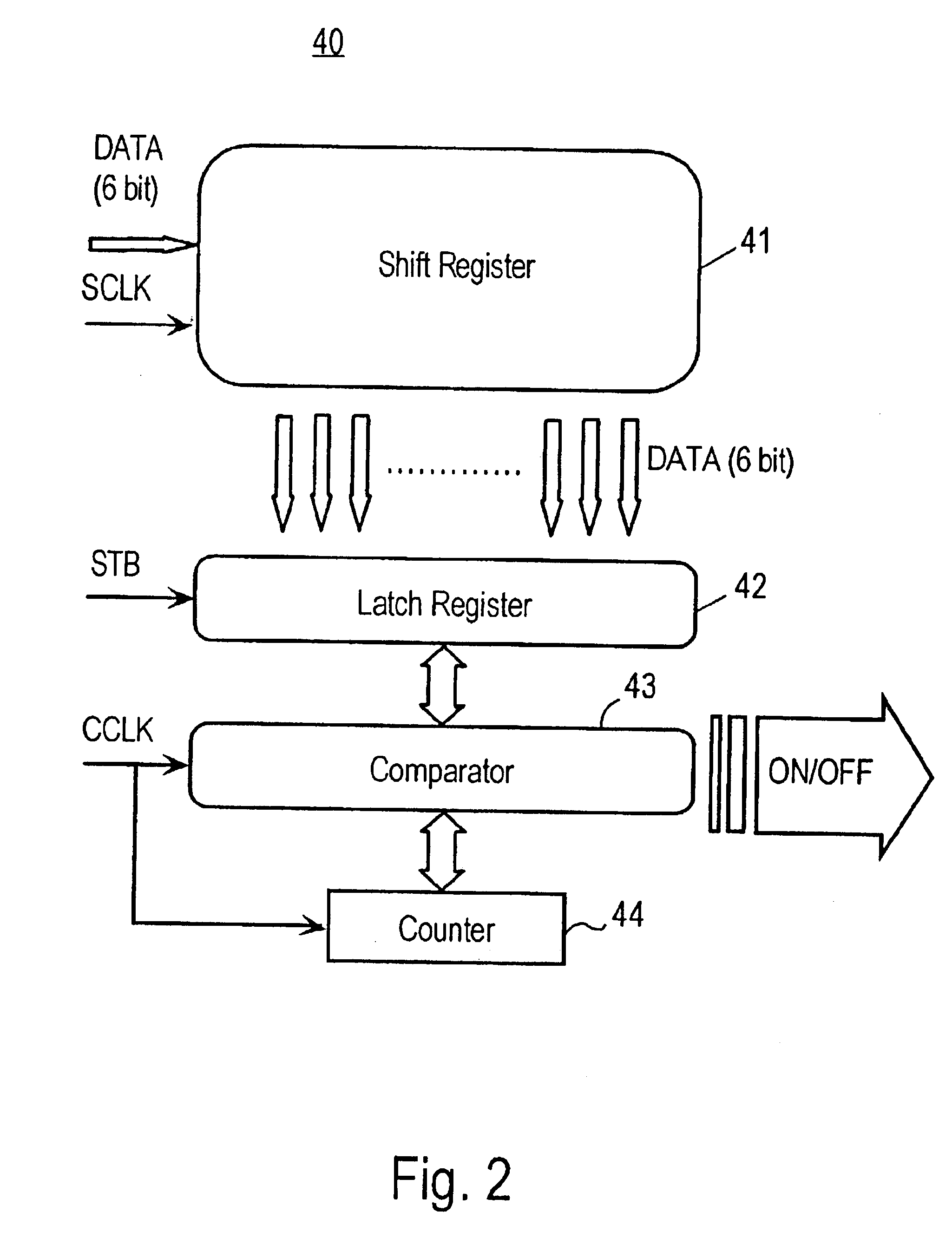
An 8-bit (256 gradient) image is represented using a driver IC of 6-bit (64 gradient) construction to drive a plurality of arrayed optical shutter elements. The image data are divided into 64 gradient sections, synchronized by shift clock signals, and transmitted in four cycles to the shift register. The optical shutter element is not turned OFF at the 64th pulse, but is continuously driven without transmitting to the comparator the standard clock signal of the 64th pulse, which controls the ON time of the optical shutter element.In this way, an image of a higher number of gradient levels can be represented using a driver IC of a low number of bits, thereby providing a solid state scanning type optical recording device which suppresses noise generation by reducing the load on the driver IC when driving at multi-level gradient.
Description
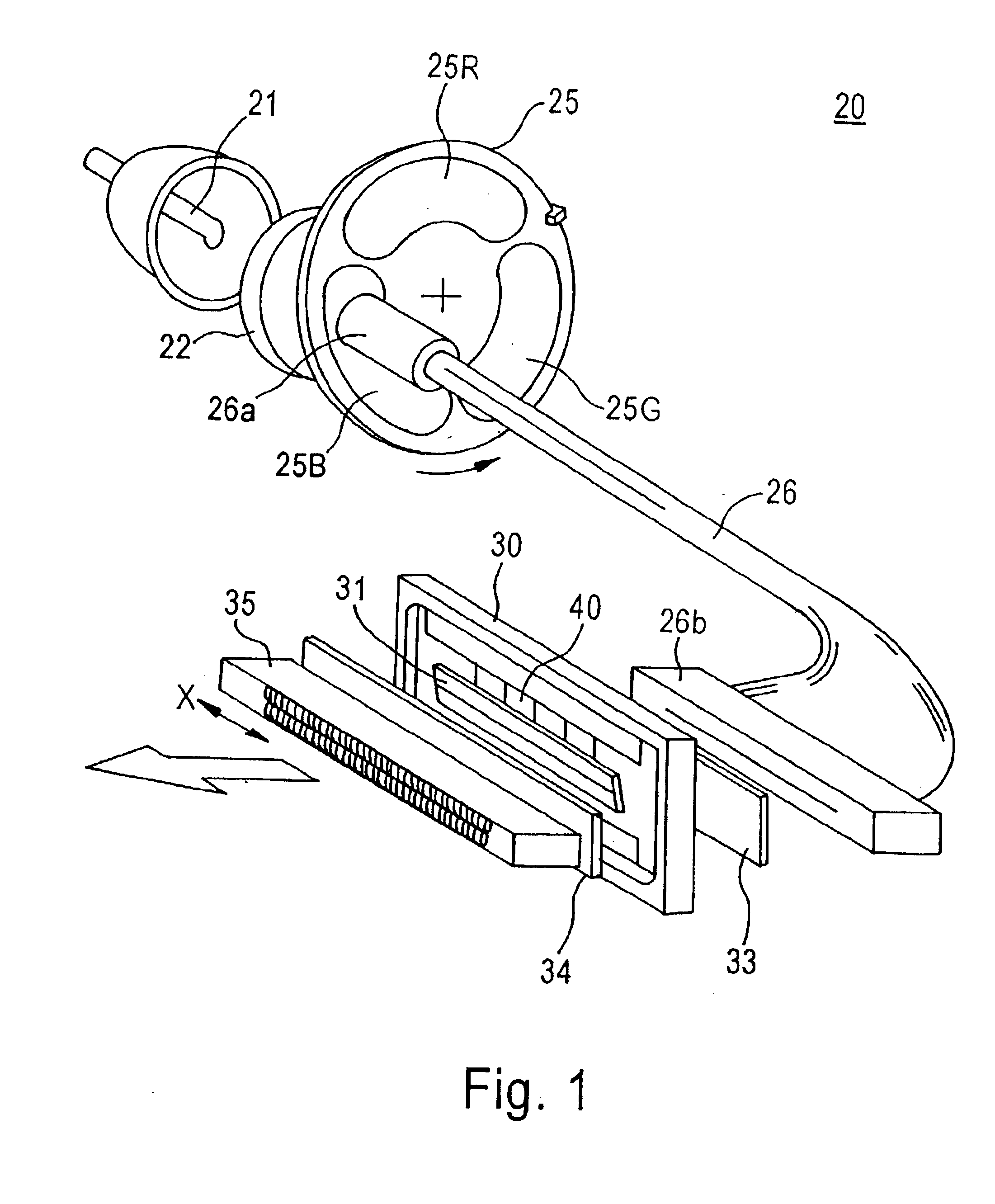
CROSS-REFERENCE TO RELATED APPLICATIONSThe present application claims priority to Japanese Patent Application No. 10-326386 filed Nov. 17, 1998, the content of which is hereby incorporated by reference.DESCRIPTION OF THE INVENTION1. Field of the InventionThe present invention relates to a solid state scanning type optical recording device for recording an image (latent image) on the surface of a photosensitive member by ON / OFF switching of light based on image data using a plurality of modules of electro-optic elements having an electro-optic effect (e.g., an optical shutter device formed of PLZT).2. Description of the Related ArtIn general, there have been various proposals for solid state scanning type optical recording devices which control the ON / OFF switching of light for individual pixels using electro-optic elements, e.g., an optical shutter element formed of PLZT, to form an image (latent image) on an electrophotographic photosensitive member, film or a printing paper having...
Claims
Login to View More Application Information
Patent Timeline
 IPC IPC(8): G06K15/12B41J2/445G02F1/055
CPCG06K15/1252
InventorMIYAGAWA, YUTA
OwnerMINOLTA CO LTD