
Bead cushioning device

a cushioning device and bead technology, applied in the field of beads in cushions, can solve the problems of high pressure on bony prominences (e.g. hip bones) and non-prominent areas, and achieve the effect of reducing pressur

Inactive Publication Date: 2005-02-22
STRYKER CORP
View PDF15 Cites 41 Cited by
  • Summary
  • Abstract
  • Description
  • Claims
  • Application Information

AI Technical Summary

Benefits of technology

The present invention is directed to a cushioning device. The cushioning device has a flexible container and a plurality of polymeric beads within the flexible container which flows under a slight force and shears easily. The cushioning device is capable of receiving a physical object that applies a force to the cushion. When the force is initially applied to the cushioning device, the cushioning device is deformed to conform to the physical object from its original shape. When the physical object is not applying the force, the cushioning device reverts to a shape that is close to but not identical to the original shape, except for a limited number of materials such as molded elastomeric materials. In addition, the pressure exerted by the cushion on the physical object will reduce pressure that would cause tissue damage and lead to decubitus ulcers.

Problems solved by technology

The elastomeric particles are not round or microspheres and, therefore, do not accommodate a sliding and rolling contact.
In that reference Pearce discloses “It is well known that persons who must sit or lie in a reclined position for extended periods of time experience localized tissue breakdown leading to decubitus ulcers (pressure sores), which in turn can lead to extensive hospital stays, and in severe cases, even amputation.
Such excessive localized external pressure often occurs when a person sits or lies on traditional cushioning devices, which can cause higher pressures on bony prominence (e.g. hip bones) than on non-prominent areas.
When the deforming object on a cushion is a portion of human body, the deforming force causes excessive pressure on body tissue which can lead to discomfort or to decubitus ulcers.
This results in the supporting forces being applied to the cushioned object over the largest possible area, resulting in the lowest possible supporting pressure.
He explains this position by stating: “A flat foam cushion is very ineffective at achieving these goals because: (1) the cushion is not originally shaped to match the contours of the object to be rested on it, and when an object is placed on the foam cushion, the foam imperfectly re-shapes to the object's contour, not utilizing the entire surface area over which the supporting force is applied; and (2) because of its memory, the foam attempts to rebound and return to its original flat shape, applying stressful pressure to the cushioned object in direct proportion to the degree to which the foam cushion has been deformed.
These pressure peaks can cause discomfort and can cause tissue damage that leads to decubitus ulcers.
This is so] because the cutting process is inherently inaccurate, precise placement of the object or person on the contoured foam cushion is difficult, movement of the object or person on the cushion defeats the benefits of the contour, and the memory of even pre-shaped finite-thickness foam causes undue pressure on body tissue and can lead to tissue damage.
Prior art fluid cushions fail to do this.
A single hammock has high peak pressures because it suspends protruding body parts on the bladder material first, placing additional pressure on those protruding parts when the full weight of the person deforms the resistive bladder further, and it does not fully conform to the contours and crevices of the cushioned body.
Unfortunately, the prior art methods of segmenting a single large bladder (i.e., selectively sealing the top bladder surface to the bottom bladder surface) created a situation in which the bladder surfaces, and hence also the fluid, were movement-restricted by these segmenting seals and could not fully conform to the irregular surface of the user's body.
This reduced the total surface area of human tissue onto which the cushioning force was applied, thus raising the average pressure and increasing the danger of tissue damage.
Also, the small number of bladder segments used by the prior art created some peak pressure areas.
Additionally, because this cushion design prevented fluid from flowing from one segment or cell of the cushion to another, pressure equalization among cells was not achieved and the danger of decubitus ulcers from high pressure spots was not eliminated.”
Applicants have, however, determined that full shape memory or little to no shape memory cushions is undesired.
Full shape memory is undesired for the reasons set forth by Pearce.
And little to no shape memory is undesired by customers because the cushion after numerous uses eventually bottoms out.

Method used


Image

  • Bead cushioning device
  • Bead cushioning device
  • Bead cushioning device

Examples


Embodiment Construction

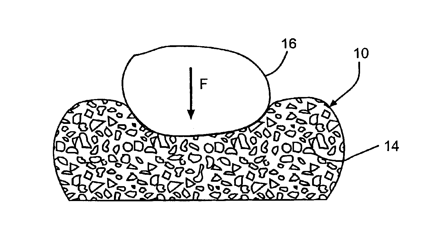
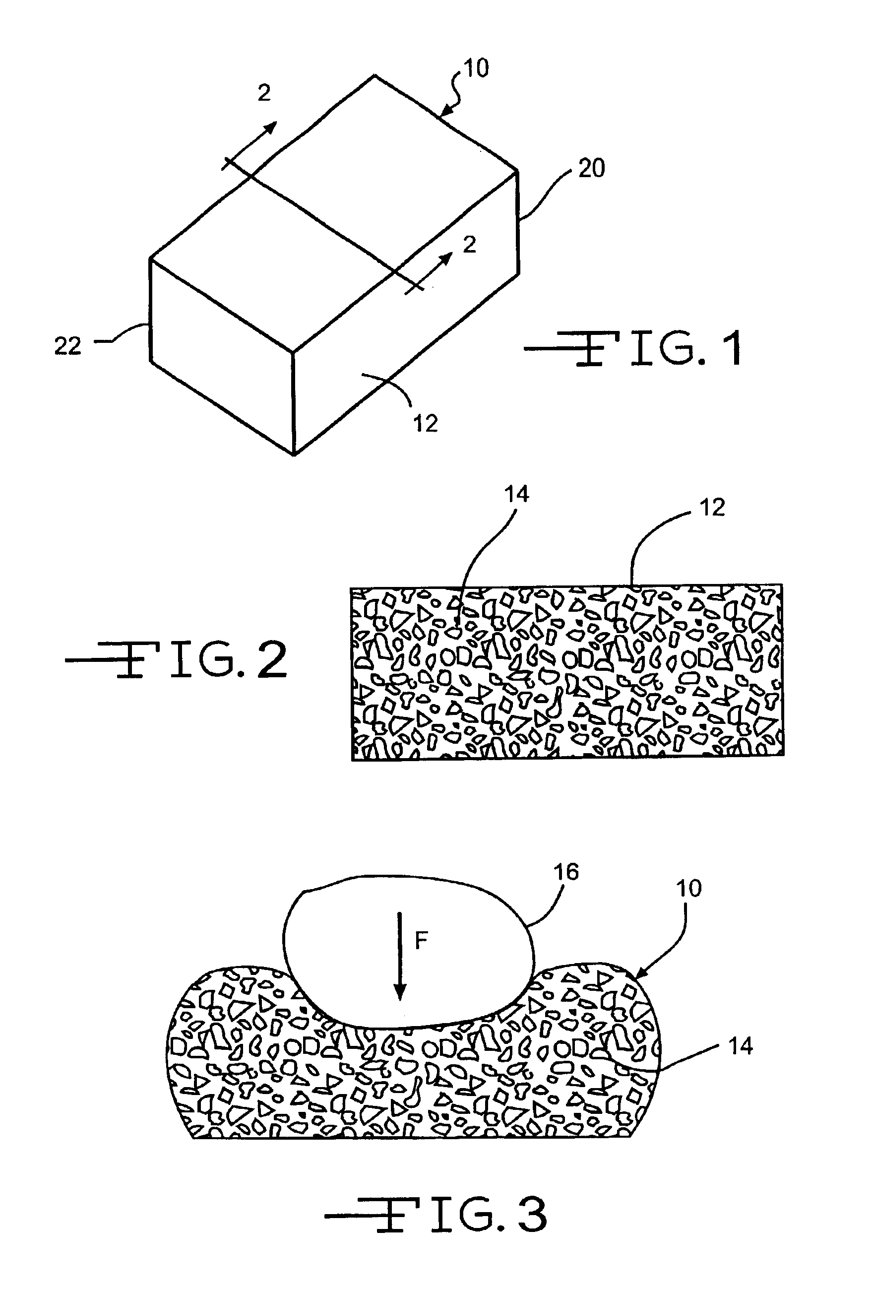
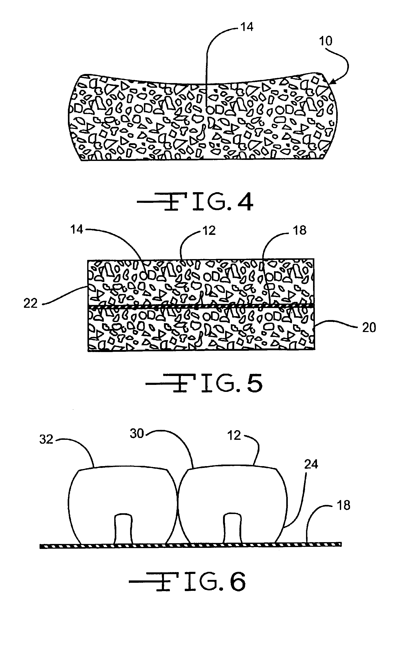
The present invention is directed to a cushioning device 10, as illustrated in FIG. 1. The cushioning device has a flexible container 12 and a plurality of polymeric beads 14, as illustrated in FIG. 2, within the flexible container 12. The beads 14 are designed to flow under a slight force and easily shear.

The cushioning device is capable of receiving a physical object 16, as shown in FIG. 3, that applies a force (F) to the cushion 10. When the force (F) is applied to the cushioning device 10, the cushioning device 10 deforms from its original shape, an example thereof is illustrated in FIG. 2, to conform about a portion of the physical object 16, as illustrated in FIG. 3.

When the physical object 16 is removed from the cushioning device 10, the cushioning device 10 reverts to a shape, see FIG. 4, that is close to but not identical to the original shape, except for a limited number of materials such as molded elastomeric materials, see FIG. 2. This means the present invention does no...


PUM


Abstract

A cushioning device has a flexible container and a plurality of polymeric beads within the flexible container which flows under a slight force and shears easily. The cushioning device is capable of receiving a physical object that applies a force to the cushion. When the force is initially applied to the cushioning device, the cushioning device is deformed to conform to the physical object from its original shape. When the physical object is not applying the force, the cushioning device reverts to a shape that is close to but not identical to the original shape, except for a limited number of materials such as molded elastomeric materials. In addition, the pressure exerted by the cushion on the physical object will reduce pressure that would cause tissue damage and lead to decubitus ulcers.

Description

FIELD OF THE INVENTIONThe invention relates to beads in a cushion.BACKGROUND OF THE INVENTIONApplicants are aware that Weile taught in U.S. Pat. No. 3,552,044 a conformable pad filled with elastomeric particles covered with a lubricant. The elastomeric particles are described by Weile at col. 2, lines 61-72; col. 3, lines 44-45 and 63-67 of the '044 patent aspellets [can be natural rubber, urethane rubber or other synthetic elastomers) about ⅛ of an inch in diameter and random length, but normally about ⅛ of an inch long, forming small cylinders that had substantially equal dimensions in all directions, which is important for good flow properties. The softer durometer material rods are usually slightly longer ranging up to ¼ inch long. In mixing, only enough of the silicone grease to thinly coat each pellet was used. Cylinders were used in this application because of their availability, low cost and their success in testing.The interior of the pad here is shown with spherical elasto...

Claims


Application Information

Patent Timeline
Patent Type & Authority Patents(United States)
IPC IPC(8): A47C27/12A47C31/12A47C31/00A61G7/057A47C27/00A61G7/05
CPCA47C27/086A61G7/05738A47C27/12
Inventor JUSIAK, JOEL T.FLICK, ROLAND E.
Owner STRYKER CORP
Learn More