Bottle-shaped can manufacturing method

Inactive Publication Date: 2005-02-22
DAIWA CAN
View PDF15 Cites 99 Cited by
  • Summary
  • Abstract
  • Description
  • Claims
  • Application Information

AI Technical Summary

Benefits of technology

A main object of the invention is to provide a bottle-shaped can manufacturing method capable of easil

Problems solved by technology

In the bottle-shaped can of this type, however, the end sheet seaming portion is located in the upper portion of the can to raise problems that dust is liable to accumulate in the concave portion inside of the seamed portion, and that the seamed portion itself protrudes to deteriorate the appearance.
Since the neck portion has a considerably smaller diameter than that of the can body, however, the diametrical reduction ratio for forming the neck portion is so large that the neck portion is difficult to constrict all at once by enlarging one drawing rate.
Thus, in the bottle-shaped can having the neck portion formed by constricting the open upper end of the can body, a number of necking machines are required to raise the cost for the facilities, and the increase in the number of working steps makes it frequent to damage or deform the can thereby to lower the quality of the can.
Although one drawing extent can be made larger than that of the neck-in working, however, there is a limit to the drawing ratio (i.e., the reduction ratio of one drawing extent).
According to the former method, however, the height of the neck portion is too short at 6 mm to form a threaded portion capable of retaining sufficient sealing properties.
These shock marks look like streaks not only to degrade the appearance but also to lower the c

Method used


Image

  • Bottle-shaped can manufacturing method
  • Bottle-shaped can manufacturing method
  • Bottle-shaped can manufacturing method

Examples


Example

A first embodiment of a method for manufacturing a bottle-shaped can of the invention will be described with reference to the accompanying drawings.

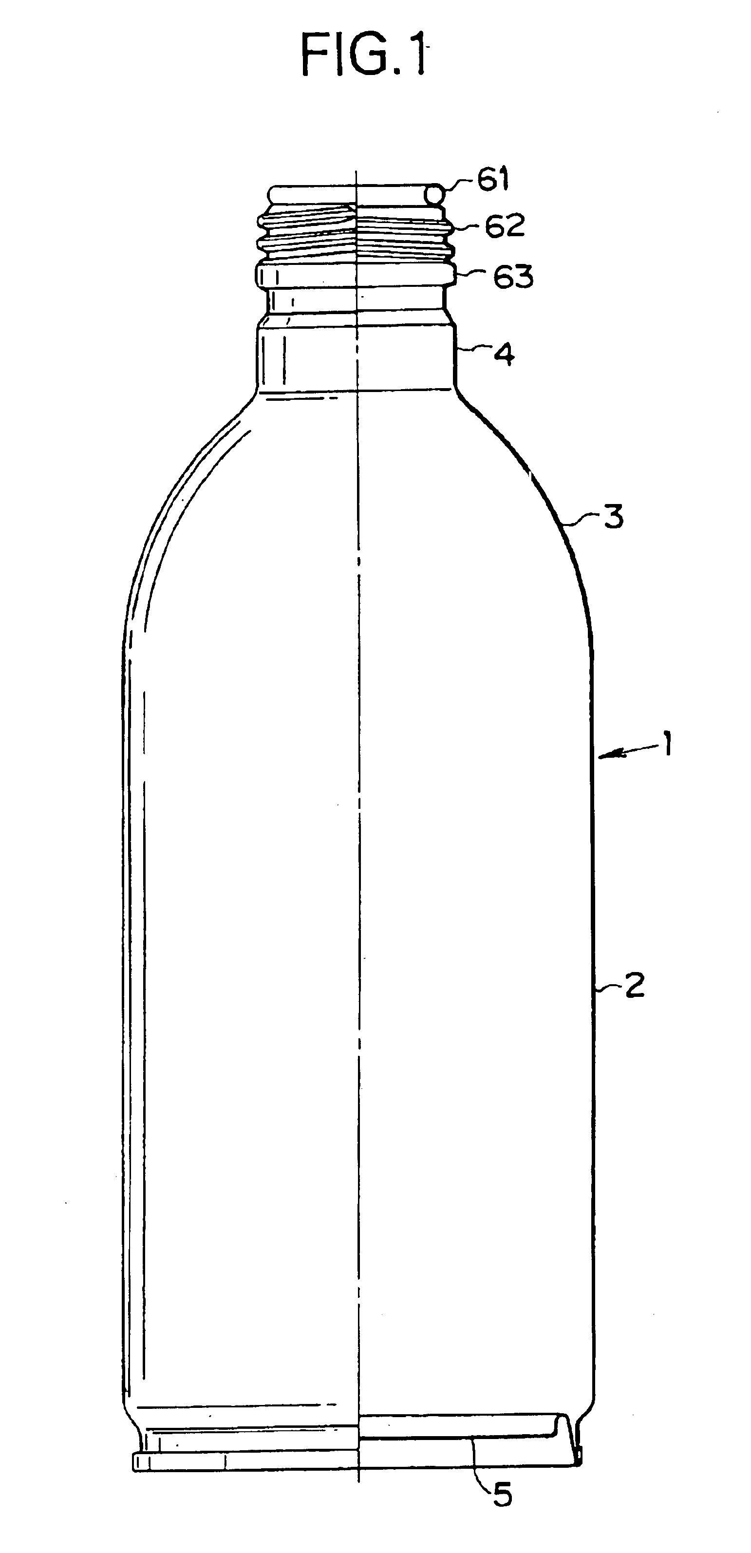
FIG. 1 shows one example of the bottle-shaped can to be manufactured by the method of the invention. The shown bottle-shaped can 1 is constructed to include: a can trunk 2 having a diametrically large cylindrical shape; a neck portion 4 having a diametrically small cylindrical shape and formed integrally with and upward from the can trunk 2 through a domed shoulder portion 3 having an arcuate longitudinal section; and a bottom end 5 seamed on the open lower end of the can trunk 2 to close the opening.

This bottle-shaped can 1 is characterized in its shape such that the shoulder portion 3 having a rounded curved slope smoothly joints the diametrically large cylindrical can trunk 2 and the diametrically small cylindrical neck portion 4. A curled portion 61 is formed at the upper end of the neck portion 4, and a threaded portion 62 is formed...

Example

Next, a second embodiment of the method for manufacturing the bottle-shaped can of the invention will be described with reference to FIGS. 9, 10 and 11.

FIG. 9 is a front elevation showing an example of a bottle-shaped can having a different shape of a shoulder portion from that of the bottle-shaped can having been described in connection with the first embodiment, with its right-hand half being in section.

On the other hand, FIG. 10 is a diagram showing drawing steps of reducing the diameter of the diametrically small cylindrical portion of the thin can which is drawn at its bottom to form the diametrically small cylindrical portion in the second embodiment of the bottle-shaped can manufacturing method of the invention.

Moreover, FIG. 11 is a diagram for explaining the shoulder portion reforming steps of reforming the shoulder portion, which has been drawn (or re-drawn) three times to form one curved shoulder face, two shallow curved concave faces and one narrow convex portion, but fo...

Example

Now, FIG. 12 shows a bottle-shaped can 301 which is manufactured by the method of a third embodiment such that its shoulder portion is formed to have a slope of a straight longitudinal section and an angle of about 45 degrees with respect to the axis of the can.

On the other hand, FIG. 13 shows such one of the steps of manufacturing the bottle-shaped can 301 of the third embodiment as re-draws the diametrically small bottomed cylindrical portion which is drawn formed from the bottom corner portion of the thin can.

This bottle-shaped can 301 is different only in the shoulder portion shape from the bottle-shaped can (having the shoulder portion of the domed curved face shape), as exemplified in the first embodiment. The re-drawing steps of the diametrically small cylindrical portion are substantially identical to those of the second embodiment, and their description will be simplified or omitted by adding a numeral “100” to the reference numerals designating the same parts or portions a...


PUM

PropertyMeasurementUnit
Fractionaaaaaaaaaa
Thicknessaaaaaaaaaa
Thicknessaaaaaaaaaa

Abstract

A bottle-shaped can manufacturing method for forming a shoulder portion having a slope and a diametrically small cylindrical neck portion integrally by further working a bottom side of a bottomed cylindrical can which is formed thinner at its trunk wall than at its bottom wall by drawing a metallic sheet having a thickness of 0.1 to 0.4 mm and by executing at least one thinning working of a bending/extending working and an ironing working.

Description

BACKGROUND OF THE INVENTION1. Field of the InventionThe present invention relates to a method for manufacturing a bottle-shaped can, of which a can trunk, a shoulder portion and a neck portion having a threaded portion are integrally formed, of a metallic sheet having a thickness of 0.1 to 0.4 mm.More particularly, the invention relates to a forming method for forming especially the shoulder portion into a smooth and beautiful slope not in a step shape or a shape having a step mark left, when the bottle-shaped can is to be manufactured by working the bottom side of the can formed into a bottomed cylindrical shape, to form the shoulder portion having an inclined annular face and a diametrically small cylindrical neck portion integrally.2. Related ArtAs beverage cans for various soft drinks or beer, there are generally employed the DI cans (Drawn 5 and Ironed cans), of which the can trunk (or side wall portion) and the can bottom are integrally formed by drawing and ironing a metallic...

Claims


Application Information

Patent Timeline
IPC IPC(8): B21D22/20B21D22/30B21D51/26
CPCB21D51/26B21D22/30
Inventor ENOKI, YASUSHI
Owner DAIWA CAN
Why Eureka
Try Eureka