

Combustion chamber dynamic pressure transducer tee probe holder and related method
a technology of dynamic pressure transducer and tee probe, which is applied in the direction of fluid pressure measurement, instruments, machines/engines, etc., can solve the problem of not being able to measure the true dynamic pressure of the combustion system, and achieve the effect of accurate and continuous measurement of the dynamic pressur
- Summary
- Abstract
- Description
- Claims
- Application Information
AI Technical Summary
Benefits of technology
Problems solved by technology
Method used
Image

Examples
Embodiment Construction
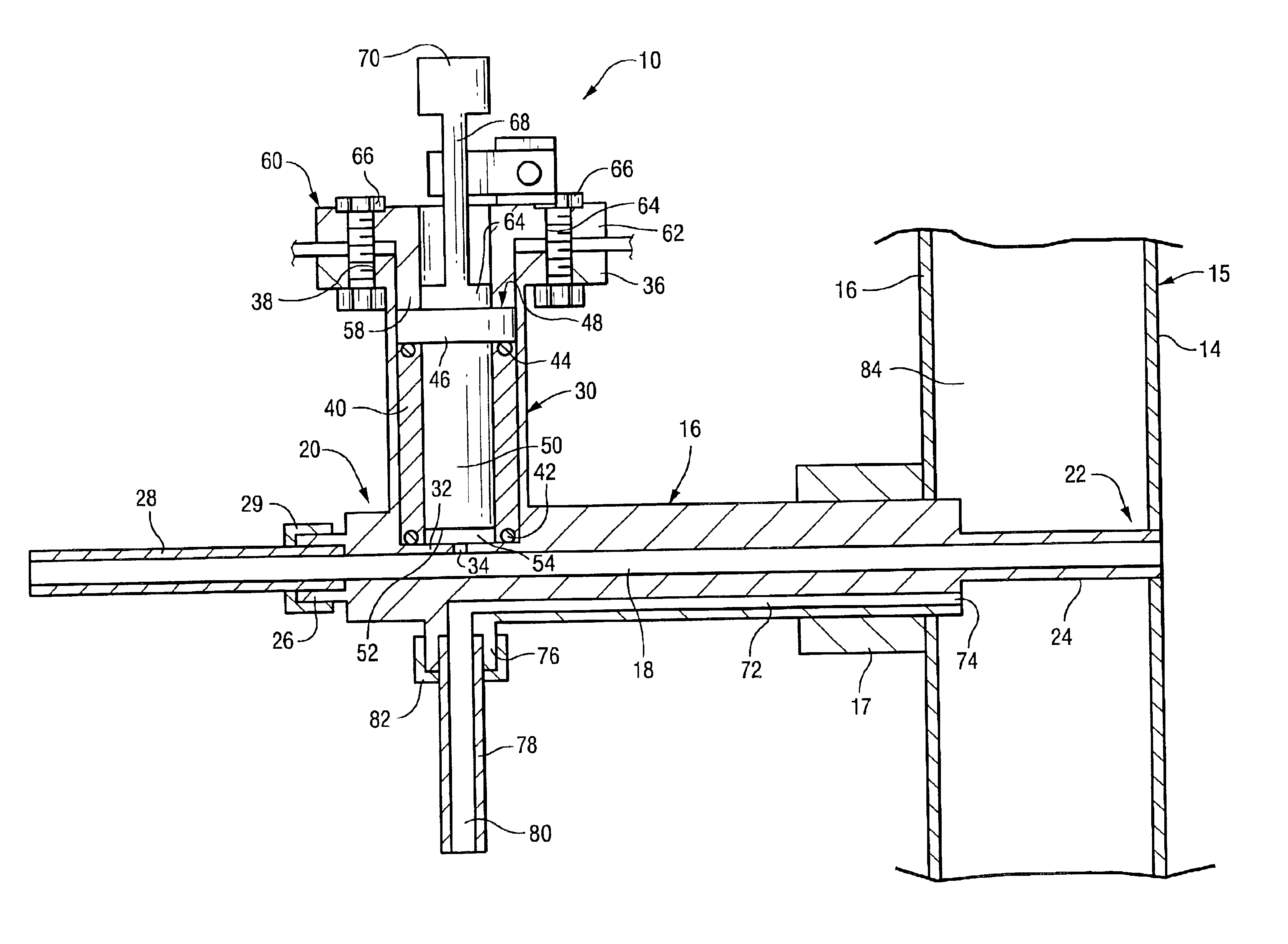
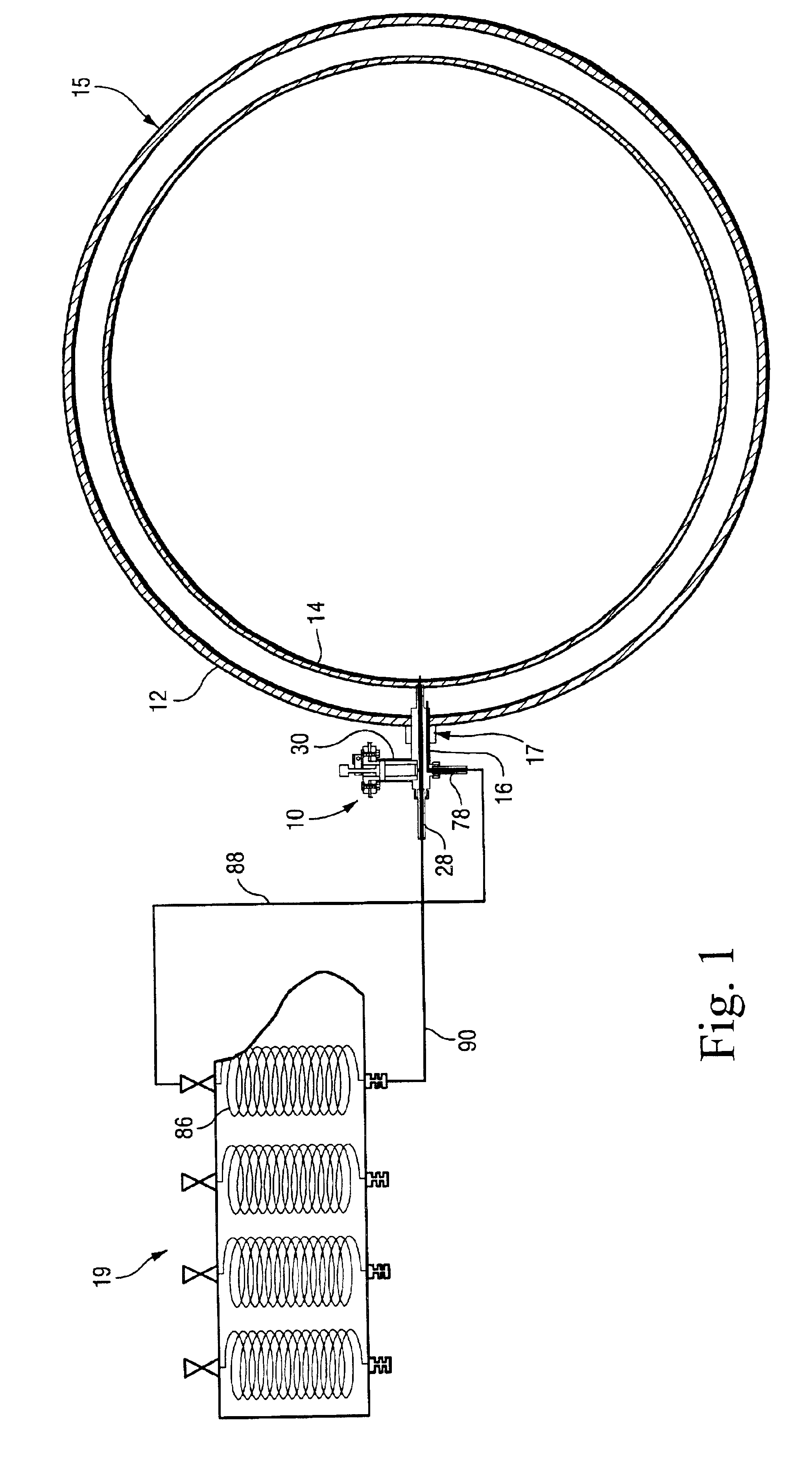
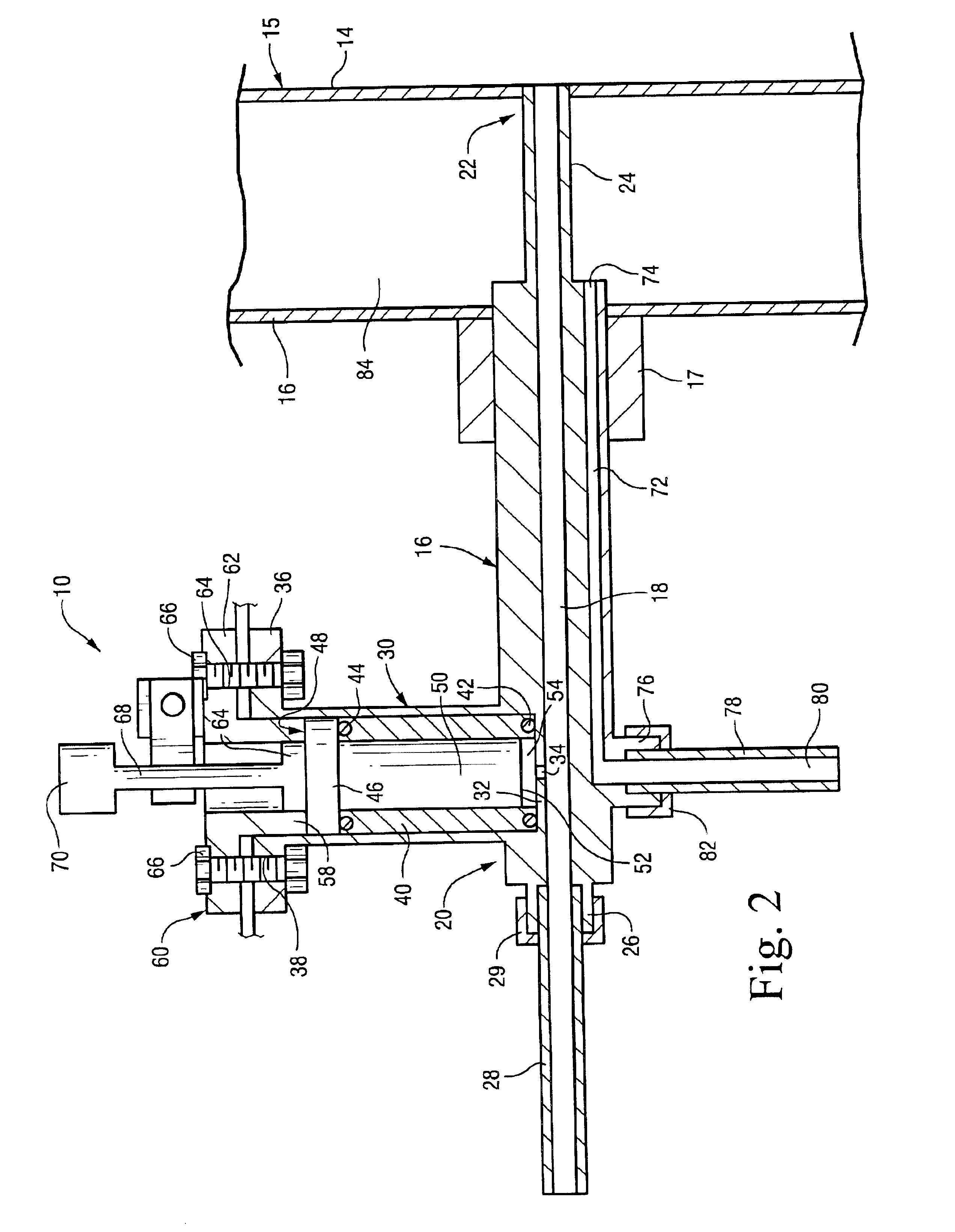
With reference to FIG. 1, the Tee probe holder 10 is shown attached to the outer wall or casing 12 of a combustor 15 via a conventional compression fitting 17. As explained further below, the forward tip of the holder 10 is seated in an aperture in the combustion liner 14 that is concentric with, and spaced radially inward of, the outer wall or casing 12. The dynamic pressure signal is transmitted through a passage 18 in the holder to a sensor located within the holder but relatively remote from the forward tip, as described in further detail below. The pressure signal is damped in a nearby acoustic damping system 19, also described further below.
With reference now also to FIG. 2, the Tee probe holder 10 includes a generally cylindrical or other suitably shaped holder body 16 formed with a first through-bore or passage 18 extending from a rearward end 20 to a forward end 22 of the holder body. The forward end 22 includes a reduced thickness forward extension 24 and the rearward end ...
PUM
| Property | Measurement | Unit |
|---|---|---|
| temperatures | aaaaa | aaaaa |
| temperatures | aaaaa | aaaaa |
| temperatures | aaaaa | aaaaa |
Abstract
Description
Claims
Application Information