Method of forming parylene-diaphragm piezoelectric acoustic transducers

a piezoelectric acoustic transducer and diaphragm technology, applied in the direction of transducer diaphragms, electromechanical transducers, instruments, etc., can solve the problems of relatively low sensitivity of micro-machined acoustic transducers made of these conventional diaphragm materials, and achieve the effect of enhancing the structural qualities of parylene diaphragm

Inactive Publication Date: 2005-02-22
UNIV OF HAWAII
View PDF7 Cites 87 Cited by
  • Summary
  • Abstract
  • Description
  • Claims
  • Application Information

AI Technical Summary

Benefits of technology

The patent describes a method where a layer of silicon nitride is added on top of another layer called parylene diaphragm. This helps improve the structure of the parylene diaphragm by making it more durable.

Problems solved by technology

The technical problem addressed in this patent is improving the sensitivity of micromachined acoustic transducers which currently use conventionally available diaphragm materials like silicon nitride or silicon, resulting in lower sensitivity.

Method used


Image

  • Method of forming parylene-diaphragm piezoelectric acoustic transducers
  • Method of forming parylene-diaphragm piezoelectric acoustic transducers
  • Method of forming parylene-diaphragm piezoelectric acoustic transducers

Examples


Embodiment Construction

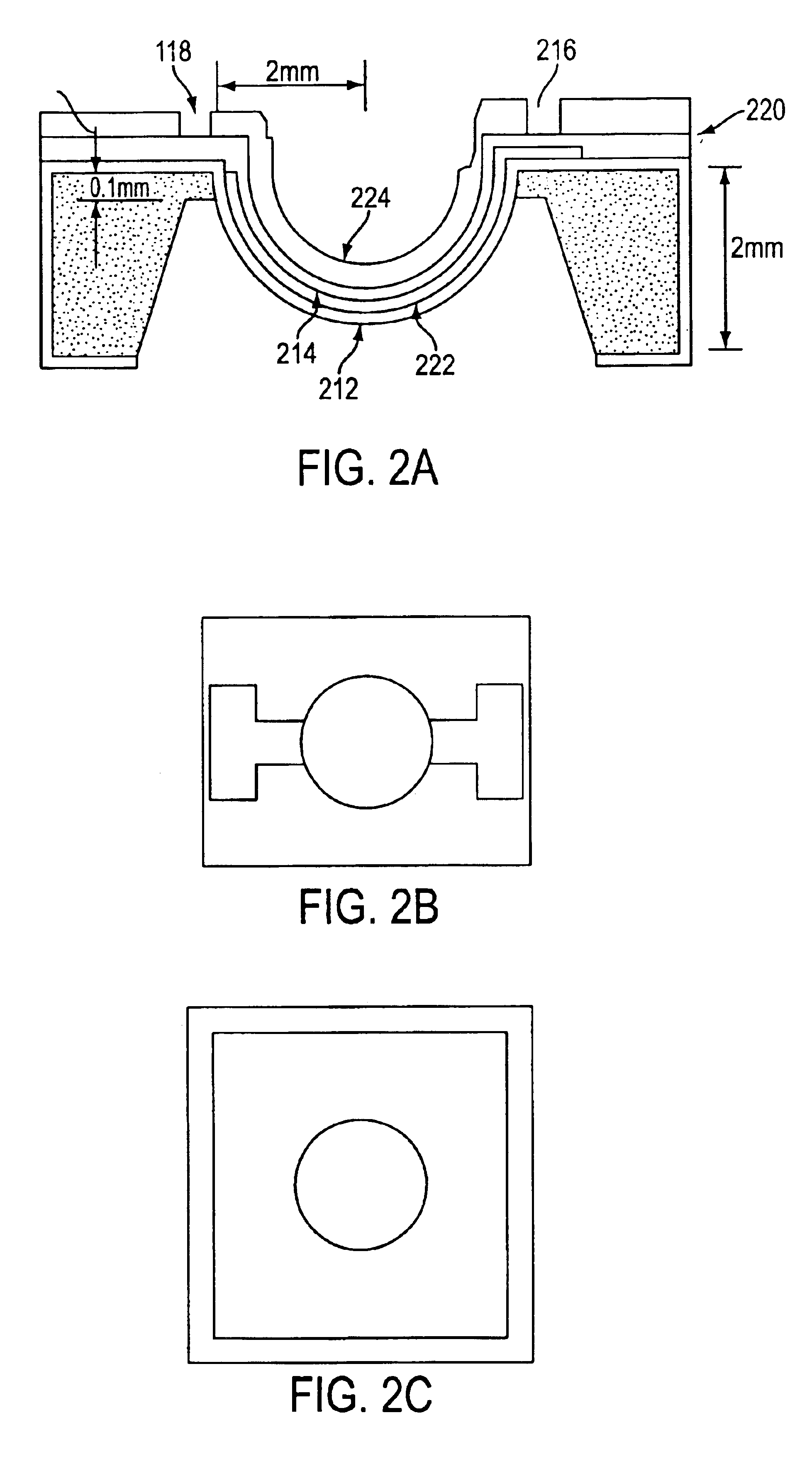
class="d_n">[0023]FIG. 2B is a top view of the parylene piezoelectric dome-shaped diaphragm acoustic transducer;

[0024]FIG. 2C is a bottom view of the parylene piezoelectric dome-shaped diaphragm acoustic transducer;

[0025]FIGS. 3A-3H are the processing steps to fabricate the parylene flat-diaphragm acoustic transducers and the parylene-held cantilever-like-diaphragm acoustic transducers;

[0026]FIGS. 4A-4H show the processing steps to fabricate the parylene piezoelectric dome-shaped diaphragm acoustic transducer with the shadow-mask patterning method;

[0027]FIGS. 5A-5F show the processing steps to fabricate the shadow mask using anisotropic and isotropic etching technique;

[0028]FIGS. 6, 7, 8, 9A-9C and 10A-10B illustrate various cantilever type parylene diaphragm acoustic transducers which can be fabricated using the technology described above.

DETAILED DESCRIPTION OF THE INVENTION

[0029]Microelectromechanical Systems (MEMS) technology has been used to fabricate tiny microphones and micro...


PUM

PropertyMeasurementUnit
Temperatureaaaaaaaaaa
Shapeaaaaaaaaaa
Electrical conductoraaaaaaaaaa

Abstract

A micromachined acoustic transducer comprising a parylene diaphragm piezoelectric transducer. The parylene diaphragm has far lower stiffness than the silicon nitride. The method for fabricating the parylene diaphragm acoustic transducer utilizes a prestructured disphragm layer utilizing silicon nitride which is compatible with high temperature semiconductor process. A silicon nitride layer is patterned and partially removed after forming the parylene diaphragm layer in order to enhance the structural qualities of the parylene diaphragm. The diaphragm may be flat or dome-shaped.

Description


Claims


Application Information

Patent Timeline
Owner UNIV OF HAWAII
Why Eureka
Try Eureka