Anti-roll suspension valve body

a technology of suspension valve and valve body, which is applied in the direction of shock absorbers, cleaning using liquids, transportation and packaging, etc., can solve the problems of obstructing the suspension port and allowing the vehicle to pass freely, and achieves the effect of reducing the ride height of the vehicle, easy installation, and quick dumping of air

Inactive Publication Date: 2005-02-22
LINK MFG
View PDF38 Cites 5 Cited by
  • Summary
  • Abstract
  • Description
  • Claims
  • Application Information

AI Technical Summary

Benefits of technology

The disc has two modes; restrictive and non-restrictive. The disc attains a non-restrictive mode when air, forcibly exhausted from an air spring, presses against the disc and compresses the coil spring. The compression of the spring causes the disc to move away from the suspension fitting, and disengages the sealing element from the suspension fitting, thereby allowing air to exhaust into the valve body through the bypass orifices as well as the central orifice. The disc attains a restrictive mode when air is injected into the suspension port from the valve body. The sealing engagement of the sealing element against the suspension fitting is reinforced so that air enters the suspension lines through the central orifice alone. Thus, when air is forced from a compressed suspension element during cornering to the valve body through a suspension port, the airflow disc associated with the suspension port connected to the compressed element attains a non-restrictive state; and air flows freely into the valve body. Conversely, when air passes through the valve body into the suspension port associated with the suspension element on the opposing, unloaded side of the vehicle, the airflow causes the airflow disc in that suspension port to substantially obstruct the suspension port, so that air cannot pass freely to the unloaded suspension port. Thus, at least for short periods of time, tilting or rolling is not exacerbated by side-to-side air transfer.
In another aspect of the invention, both airflow discs attain a nonrestrictive state to promote rapid dumping of air simultaneously from the suspension elements to lower the ride height of the vehicle.
In a third aspect of the present invention, the airflow discs are easily installed and maintained in conventional valve bodies. The airflow discs are disposed within the suspension ports between an internal seat of the valve body and an external fitting associated with an air supply line leading to the suspension elements.
In a second embodiment of the invention, a system or pneumatic circuit of solenoids and one-way valves actively restrict side-to-side air transfer. Suspension elements on opposite sides of a vehicle, a supply port and dump port are plumbed into a system including solenoids and multiple check valves. A first solenoid may be selectively actuated (a) to allow air into the suspension elements through the supply port or (b) to prevent air from escaping the system through the supply port. A second solenoid may be selectively actuated (a) to dump air from the suspension elements through the exhaust port or (b) to prevent air from escaping the system through the exhaust port.
In this second embodiment, the check valves are oriented in the system so that when suspension elements on one side of the vehicle exhaust air therefrom, such as during cornering, that air is restricted by the check valves and will not rapidly transfer through the system to the suspension elements on the other side. The solenoids act in concert with the check valves to restrict side-to-side transfer, and prevent air from being lost or input into the system during side-to-side transfer and under even-load conditions.

Problems solved by technology

Conversely, when air passes through the valve body into the suspension port associated with the suspension element on the opposing, unloaded side of the vehicle, the airflow causes the airflow disc in that suspension port to substantially obstruct the suspension port, so that air cannot pass freely to the unloaded suspension port.

Method used


Image

  • Anti-roll suspension valve body
  • Anti-roll suspension valve body
  • Anti-roll suspension valve body

Examples


first embodiment

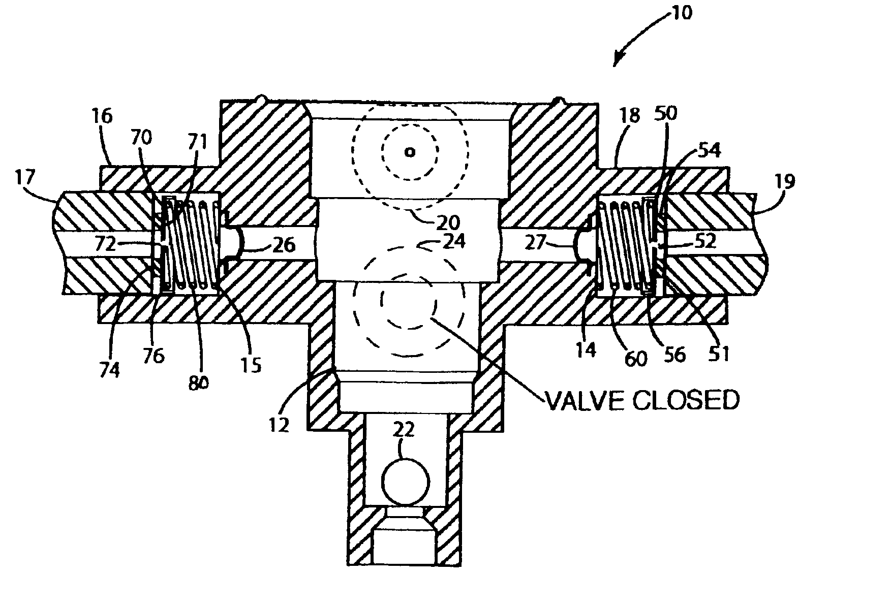
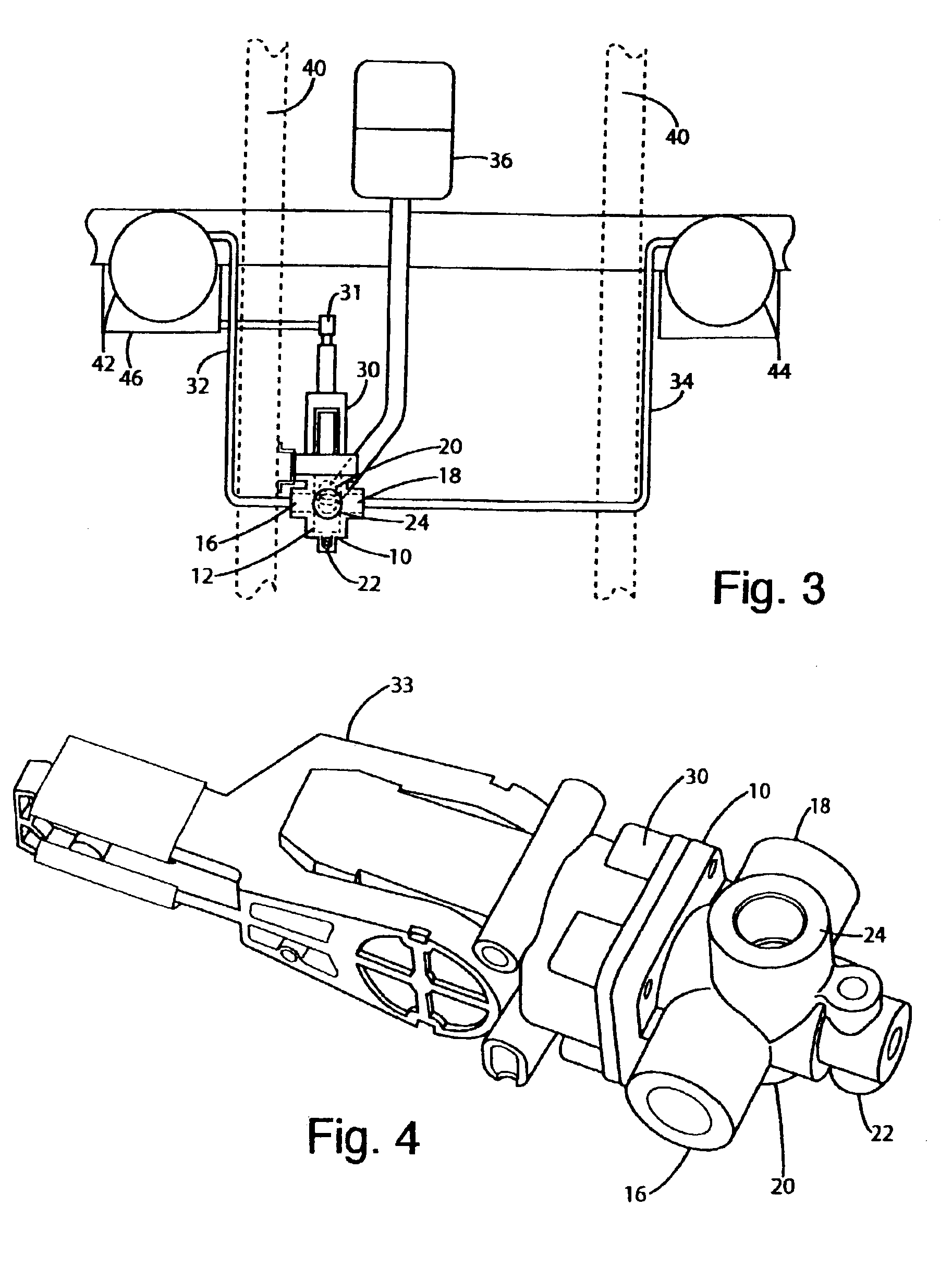
A valve body according to the present invention is illustrated in FIGS. 3, 4 and 7-10 and generally designated 10. For purposes of disclosure, the valve body 10 is described in connection with a conventional leveling system where the valve mechanism 30 couples to valve body 10 where the valve mechanism functions to control the flow of air into and out of the suspension elements 42, 44 through valve body 10 (see FIG. 3). The valve body is well suited for use in a variety of other leveling systems besides suspension, such as conventional truck cab leveling systems designed to level the truck cab with respect to the truck frame.

The leveling system of the present invention generally includes valve body 10 coupled to a valve mechanism 30 including an actuator yoke 33. The valve mechanism 30 is mounted to the vehicle frame 40 in a conventional manner and connected to the axle 46 or any other part suspension via actuator yoke 33. The actuator yoke 33 may be mounted to virtually any element...

fourth embodiment

In operation, the (1) prevents completely unrestricted side-to-side air transfer in suspension elements of a vehicle, for example, from element 242 to element 244 or vice versa; (2) fills the suspension elements at a rate somewhat less than the rate of the previously described embodiments to increase ride height; and (3) rapidly dumps air from the suspension elements to lower ride height. Under normal conditions, when the suspension elements and are under equal loads, the system is static.

During cornering, for example, taking a hard left turn, right suspension element 242 would be subjected to a tremendous force, and would try to compensate by expelling air therefrom. With reference to FIG. 15, if suspension element 242 expels air into suspension line 232, that air travels unrestricted through one-way valve 454. Thereafter, the air cannot go through one-way valve 455 and enter left side suspension line 234, because that valve is forced closed to prevent air flow therethrough. The a...


PUM


Abstract

A suspension system that restricts side-to-side airflow between air springs on opposite sides of a vehicle or trailer. In one embodiment, active airflow discs in suspension ports of a valve operate in two modes; restrictive and non-restrictive. A disc attains a non-restrictive mode when air is exhausted from an air spring. A disc attains a restrictive mode when air is injected into the suspension port from the valve toward an air spring. Airflow discs in opposing suspension ports both attain a non-restrictive state to rapidly dump air from the springs and lower vehicle ride height. In another embodiment, a pneumatic circuit includes one-way check valves, in fluid communication with opposing air springs, aligned to restrict airflow between the opposing springs under uneven loading conditions. A pair of electronic solenoids acts in concert with the check valves to selectively inflate or deflate the air springs.

Description

BACKGROUND OF THE INVENTIONThe present invention relates to a leveling system for a vehicle, and more particularly to a valve body for distributing air to suspension elements.Conventional leveling systems are installed in a wide variety of vehicles ranging from passenger cars to semi-trucks and semi-trailers. The larger leveling systems typically include pneumatic suspension elements, such as shocks or air springs, that can be inflated or deflated to control the height of the frame with respect to the axle. For example, on semi-trailers, heavy loads can cause a suspension to sag, thereby decreasing the distance between the frame and the axle. Accordingly, the ride height of the trailer, that is, the distance between the trailer bed and the ground, may be reduced. In conventional leveling systems, the ride height of the trailer may be adjusted by inflating or deflating the pneumatic suspension to compensate for the load. Specifically, when the ride height of a trailer has been affect...

Claims


Application Information

Patent Timeline
Patent Type & Authority Patents(United States)
IPC IPC(8): B60G17/04B60G17/052B60G21/00B60G21/10
CPCB60G17/0528B60G21/106B60G2202/152B60G2800/012B60G2204/8304B60G2300/04B60G2500/2046B60G2204/82Y10T137/043
Inventor SORUM, ROBERT D.SCHAFER, GARY L.TRUDEAU, CURTIS A.WINTER, DICK E.
Owner LINK MFG
Why Eureka
Try Eureka