Splined honeycomb seals

a honeycomb seal and spline technology, applied in the field of sealing, can solve the problems of limited ability of the seal to minimize leakage by maximizing rub depth and/or minimizing the gap, negative effect of secondary flow into the gas path of the turbine, and affecting the performance, efficiency and component life of the engine, so as to increase the temperature of the knife edge seal and honeycomb seal, increase the sealing engagement, and increase the sealing engagement

Active Publication Date: 2016-07-21
RTX CORP
View PDF6 Cites 4 Cited by
  • Summary
  • Abstract
  • Description
  • Claims
  • Application Information

AI Technical Summary

Benefits of technology

[0011]The seal assembly can include a rotor mounted for rotation relative to the carrier, wherein the rotor includes a knife edge seal component sealingly engaged to the honeycomb seal. The knife edge seal component can have a coefficient of thermal expansion different from that of the honeycomb seal. For example, the knife edge seal component can have a higher coefficient of thermal expansion than that of the honeycomb seal for increasing the sealing engagement with increasing temperature of the knife edge seal component and honeycomb seal.

Problems solved by technology

The loss of secondary flow into the gas path of a turbine has a negative effect on engine fuel burn, performance, efficiency, and component life.
The ability of the seal to minimize leakage by maximizing rub depth and / or minimizing the gap is limited by the relative radial thermal growth of the two components during engine operation and the minimum cold assembly gap required to enable assembly under worst-case part tolerances and other assembly considerations.
As a result of having similar CTE's, a desired or beneficial condition of having the knife edge seal grow closer or abut into the honeycomb seal is not achievable.
Such a configuration is often not desirable or even possible, e.g., in applications with design space limitations or due to other considerations such as vibration.

Method used


Image

  • Splined honeycomb seals
  • Splined honeycomb seals
  • Splined honeycomb seals

Examples


Embodiment Construction

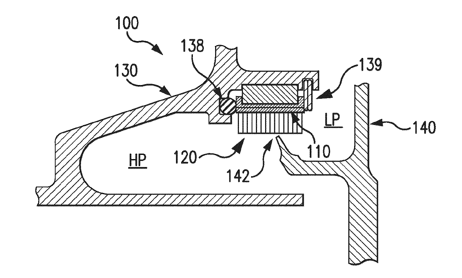
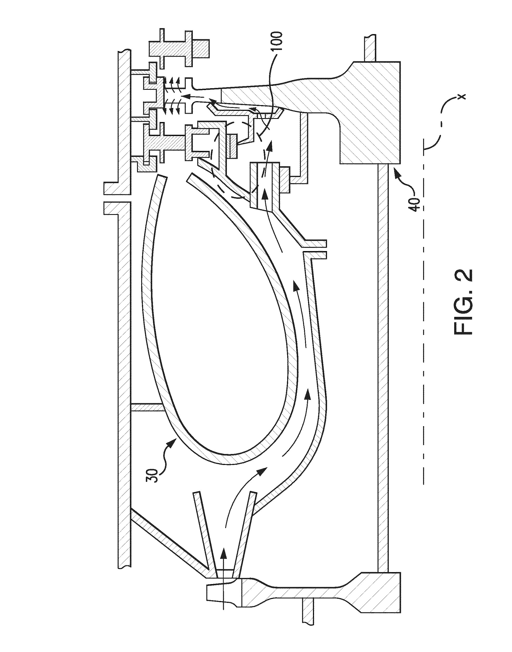
[0020]Reference will now be made to the drawings wherein like reference numerals identify similar structural features or aspects of the subject disclosure. For purposes of explanation and illustration, and not limitation, a partial view of an exemplary embodiment of the seal assembly in accordance with the disclosure is shown in FIG. 2 and is designated generally by reference character 100. Other embodiments of seal assemblies in accordance with the disclosure, or aspects thereof, are provided in FIGS. 1 and 3-5, as will be described. The systems and methods described herein can be used to provide sealing in thermal expansion and contraction environments such as in sealing between chambers in gas turbine engines.

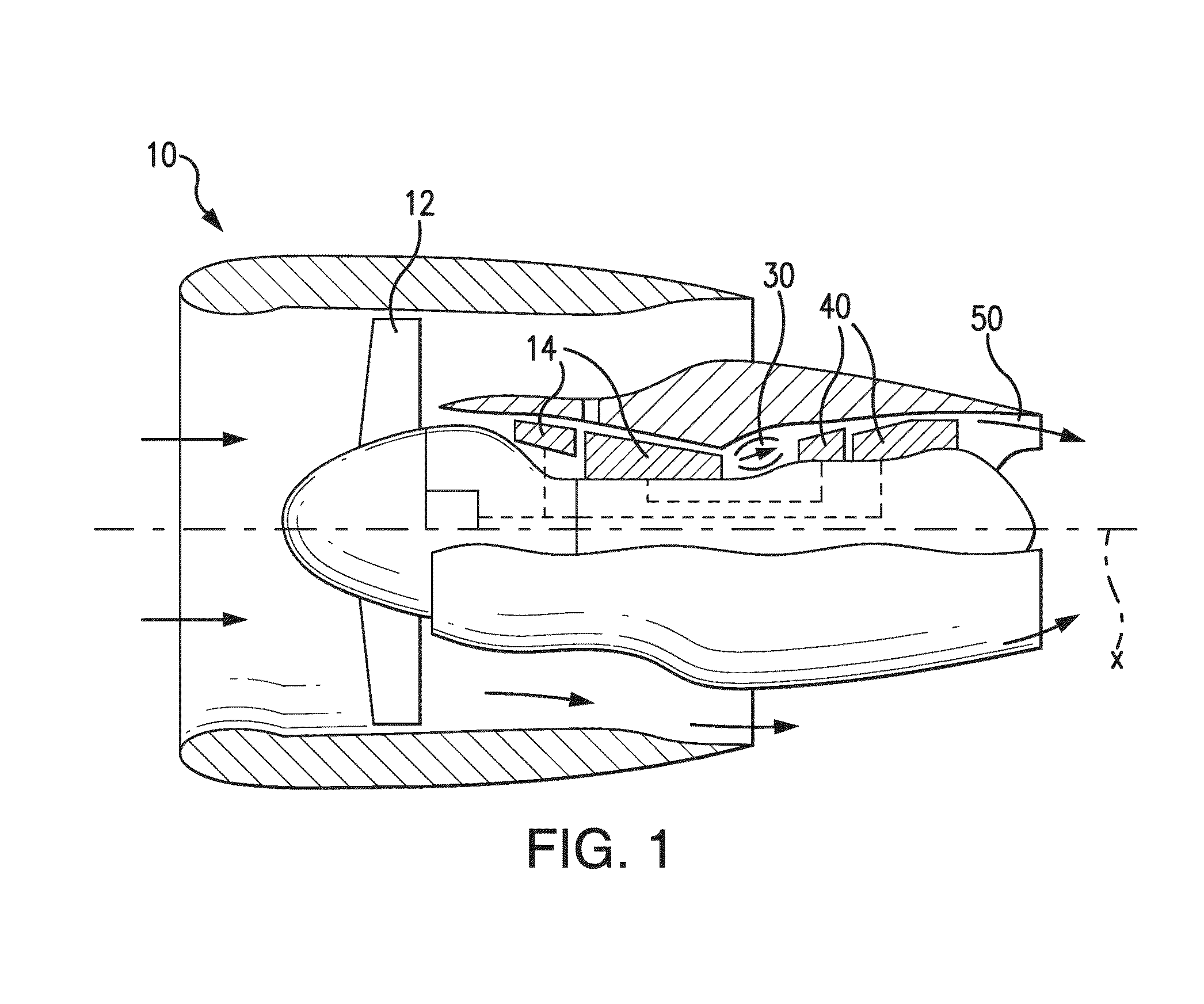
[0021]FIG. 1 schematically illustrates an example of a gas turbine engine 10 including a fan section 12, a compressor section 14, a combustor section 30, and a turbine section 40. The gas turbine engine 10 is circumferentially disposed about an engine centerline X. During op...


PUM


Abstract

A seal assembly includes an annular carrier defining a radially inward face, and an opposed radially outward face defining a plurality of spline slots. The spline slots are configured and adapted to receive corresponding spline tabs to center the carrier in a surrounding structure. A honeycomb seal is mounted to the radially inward face of the carrier. The honeycomb seal is configured for sealing engagement with a knife-edge seal rotating relative to the honeycomb seal. The seal assembly has a relatively low coefficient of thermal expansion in comparison to the static component or the knife-edge seal. For example, a gas turbine engine can include a seal assembly as described above, wherein the carrier is mounted to a static component and a rotor mounted for rotation relative to the carrier, and wherein the rotor includes the knife edge seal component sealingly engaged to the honeycomb seal.

Description

RELATED APPLICATIONS[0001]This application claims the benefit of and priority to U.S. Provisional Patent Application No. 61 / 879,310 filed Sep. 18, 2013, the contents of which are incorporated herein by reference in their entirety.BACKGROUND OF THE INVENTION[0002]1. Field of the Invention[0003]The present disclosure relates to seals, and more particularly to seals such as used in gas turbine engines.[0004]2. Description of Related Art[0005]The loss of secondary flow into the gas path of a turbine has a negative effect on engine fuel burn, performance, efficiency, and component life. A seal including of a rotating knife edge seal in close proximity to a honeycomb seal is commonly used in turbo-machinery. The ability of the seal to minimize leakage by maximizing rub depth and / or minimizing the gap is limited by the relative radial thermal growth of the two components during engine operation and the minimum cold assembly gap required to enable assembly under worst-case part tolerances a...

Claims


Application Information

Patent Timeline
Patent Type & Authority Applications(United States)
IPC IPC(8): F16J15/34F01D11/00
CPCF16J15/3496F16J15/3464F05D2250/283F05D2240/55F05D2220/32F01D11/003F02C7/28F01D11/001F01D11/08F01D11/12F01D11/122F01D11/125F01D11/127F01D11/22F01D9/02F16J15/444
Inventor DAVIS, TIMOTHY M.ANASTAS, JEFFREY VINCENT
Owner RTX CORP
Why Eureka
Try Eureka