Drill bit with pilot point

a pilot point and drill bit technology, applied in the direction of twist drills, manufacturing tools, wood boring tools, etc., can solve the problems of affecting the accuracy of drilling holes, the drill bit is subject to great strain, and the drill bit is often heavily worn, so as to achieve the effect of negative effect on drilling

Inactive Publication Date: 2005-02-22
SANDVIK INTELLECTUAL PROPERTY AB
View PDF16 Cites 46 Cited by
  • Summary
  • Abstract
  • Description
  • Claims
  • Application Information

AI Technical Summary

Benefits of technology

The above-described relationship between the extension of the base of the drill bit and the diameter of the drill bit as well as the inclination of the cutting edges axially rearwardly towards the center of the drill means that the radial forces are decreased at the same time as coating of the drill with chips is avoided. With a pilot point angle of 90°, a sharp point that comprises the center tip and a chip face, is obtained. The pilot point angle is defined as the angle between a line in the normal direction of the drill axis and the side of the center tip, and is here designated (η). Since the drill bit is preferably made double-cutting, there will be enough space to remove the chips.
This design of the cutting edges, and the above-defined shape form and extension of the tip angle, means that the center pilot tip hits the workpiece first. Thus, vibrations and movements of the drill are stabilized before the cutting edges start working the material. The distance between center pilot tip and edge ends should thus not be too long, especially if the drill bit is to be used for thinner metal sheets. The center pilot tip then presses down and deforms the metal sheet before the cutting edges engage with the metal sheet and can even cause the metal sheet to be split open. The angle of the cutting edges is not allowed to be too steep, because this would shorten the service life of the cutting edges.
According to another preferred embodiment of the drill bit, the cutting edge can also have a secondary angle of clearance of 25±5° in relation to a plane normal to the drill axis. This secondary angle of clearance is here designated (θ). Owing to such a two-part clearance described above (i.e., primary and secondary clearances), the drill obtains a more continuous transition from the cutting edges down towards the helical guiding edges. This design provides space for removing chips and other residual products. By enabling a quick and efficient removal of the chips, the risk of local imperfections and high frictional heat is reduced.

Problems solved by technology

When drilling in metal, the drill bit is subjected to great strain.
The drill often gets heavily worn, which quickly affects the accuracy in the making of holes.
This type of drill is often strong but brittle at the same time and often causes the drill to be coated with chips from the tougher material in which the drill operates.
This coating with chips means that the difference between the desired and the achieved accuracy in bore diameter often deviates significantly.
For metal and especially industrial working of various metals, completely different material properties of the drills are required since, on the one hand, they must often satisfy stricter standards of quality and demands and, on the other, they are subjected to heavier wear and greater forces than other types of drills.
When drilling in metal, also the drilling spindle and its bearings are subjected to great strain as a result of great radial forces, which makes it necessary for the drilling spindle to be serviced or even changed on frequent occasions.
The problem of achieving high quality of the worked material without simultaneously obtaining excessive radial forces, which shortens the service life of both drills and spindles, thus remains to be solved when drilling metal.

Method used


Image

  • Drill bit with pilot point
  • Drill bit with pilot point
  • Drill bit with pilot point

Examples


Embodiment Construction

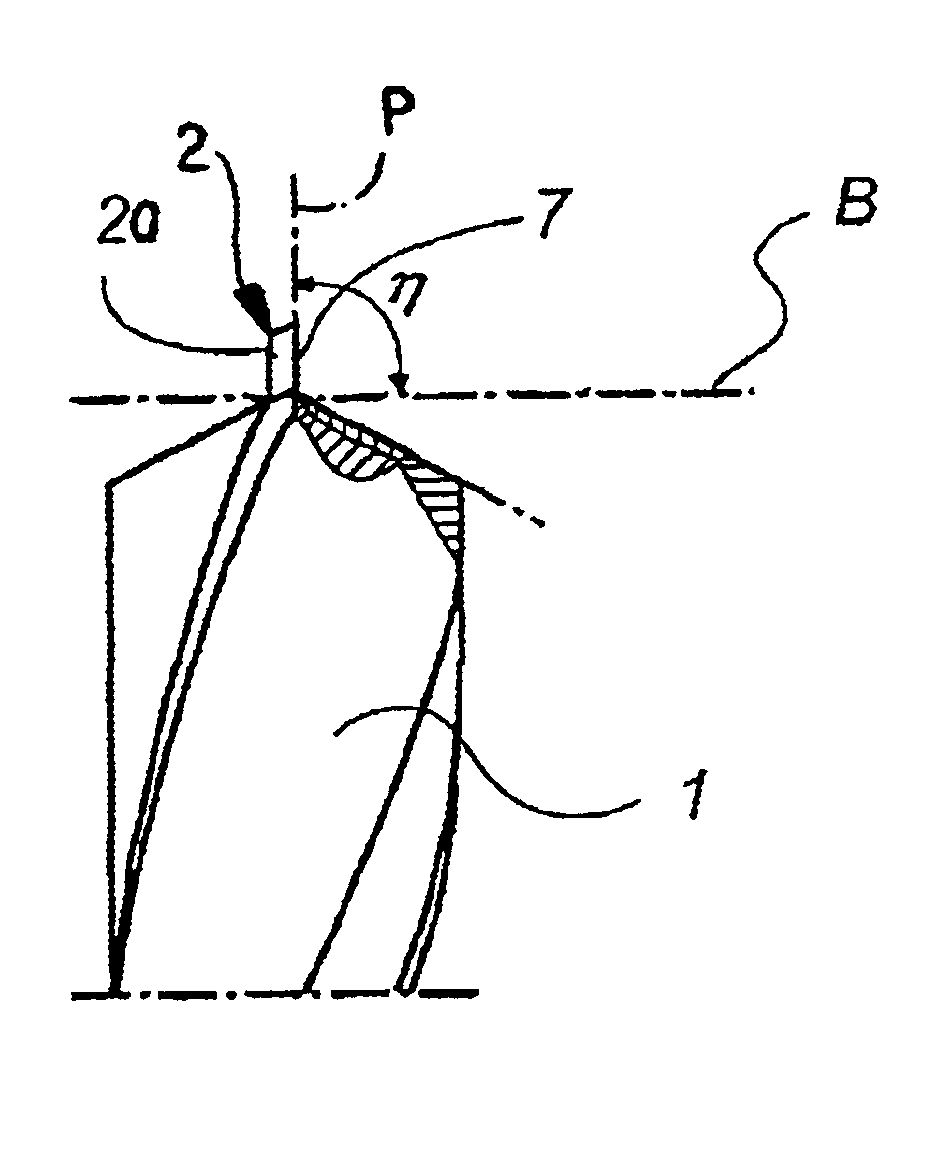
FIG. 1 is a side view of a drill bit 1 according to a preferred embodiment of the invention. The drill bit 1 is mainly intended for the working of brass, copper and light metals, such as aluminum. Also alloys with light metal are regarded as light metals. The drill bit is advantageously included in a drill made of a piece of hard metal or similar material. The drill is suitably ground in order to achieve its proper form.

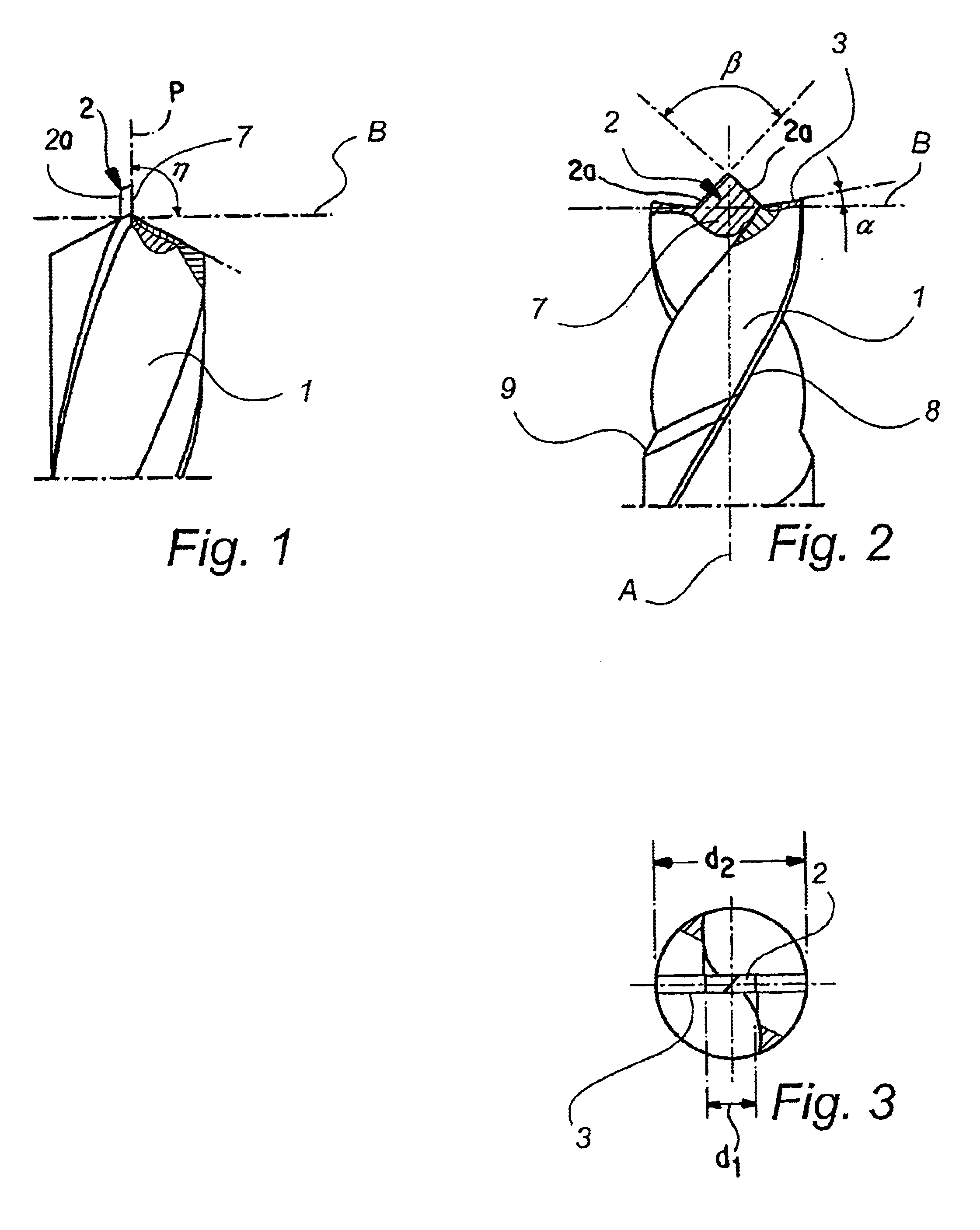
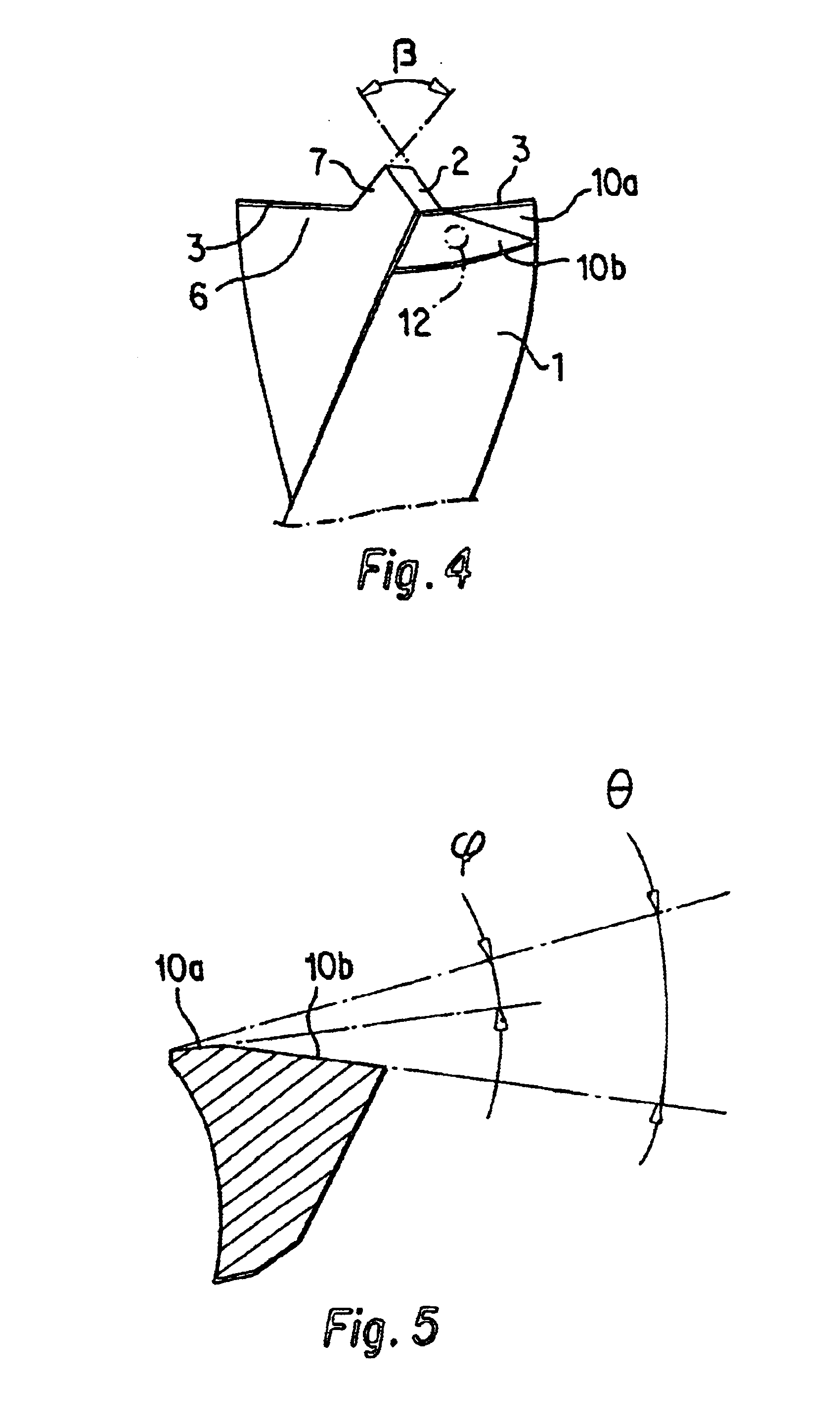
In FIG. 1, the center tip 2 is shown from the side having a pilot point angle (η) of essentially 90±2°. The angle (η) is defined as the angle between a reference plane B normal to the axis A of the drill and reference a plane P which contains both a side 7 of the pilot center tip 2 and a respective chip face 6 of the drill (see also FIG. 4).

From FIGS. 4 and 5 is can be seen that the drill includes a clearance surface structure located behind each of two straight cutting edges 3 of the drill (with reference to the direction of the rotation). In the depicted embodiment...


PUM

PropertyMeasurementUnit
cutting anglesaaaaaaaaaa
tip angleaaaaaaaaaa
angleaaaaaaaaaa

Abstract

A drill bit for the working of metal has a center pilot tip that transforms into straight cutting edges extending towards the outer periphery of the bit. Each cutting edge forms a cutting angle of 1-20° with a reference plane oriented perpendicular to of the drill axis. Each a cutting edge is inclined in a radially inward and axially rearward direction toward the drill axis. The center tip forms a pilot point angle of 90±2° and a has base that takes up 23-45 percent of the total diameter of the cutting section of the drill bit. The tip has a tip angle of 90±10°.

Description

BACKGROUND OF THE INVENTIONThe present invention relates to a drill for working metal.TECHNICAL BACKGROUNDWhen drilling in metal, the drill bit is subjected to great strain. The drill often gets heavily worn, which quickly affects the accuracy in the making of holes. One way of trying to solve the problem has been to use hard materials for manufacturing the drill bits. This type of drill is often strong but brittle at the same time and often causes the drill to be coated with chips from the tougher material in which the drill operates. This coating with chips means that the difference between the desired and the achieved accuracy in bore diameter often deviates significantly.Moreover, great demands are placed on the service life of the drill and the quality of the result when using the drill, in particular as regards industrial use. EP 0 761 352 (corresponding to U.S. Pat. No. 6,113,321) discloses a drill which is designed with a certain reduction of the consumption of material and ...

Claims


Application Information

Patent Timeline
Patent Type & Authority Patents(United States)
IPC IPC(8): B23B51/02B23B51/00
CPCB23B51/02B23B2251/14Y10T408/9065Y10T408/9097Y10T408/899
Inventor NYG.ANG.RD, EERO
Owner SANDVIK INTELLECTUAL PROPERTY AB
Why Eureka
Try Eureka