Illuminating unit having diffusion means

a technology of diffusion means and illumination units, which is applied in the direction of mechanical equipment, instruments, printers, etc., can solve the problems of insufficient mechanical strength of the frame, difficult frame work, and increase in manufacturing costs, and achieve the effect of reducing manufacturing costs, reducing manufacturing costs, and reducing manufacturing costs

Inactive Publication Date: 2005-02-22
CANON KK
View PDF14 Cites 96 Cited by
  • Summary
  • Abstract
  • Description
  • Claims
  • Application Information

AI Technical Summary

Benefits of technology

Another object of the invention is to provide an image reading apparatus of a high mechanical strength.
Further another object of the invention is to suppress a variation in reading lines due to a deviation of an optical axis.
With the above construction, a cross sectional area of the illuminating means is small and an enough mechanical strength can be assured while miniaturizing the apparatus. Further, by certainly positioning the illuminating means, a variation in reading line can be suppressed and an image can be read at a high quality.

Problems solved by technology

(1) To enclose the illuminating unit into the frame, it is necessary that a length of diagonal line in the cross section of the housing of the illuminating unit is assured in the vertical direction in the frame. However, the image sensor main body cannot be largely formed. Therefore, a thickness of frame with which the lower portion of the illuminating unit is come into contact has to be made thin. It is difficult to work the frame. Even if the frame can be worked, a mechanical strength of the frame is insufficient.
(2) An angle at which the illuminating unit is attached to the frame is not equal to 45° depending on an individual difference of each image sensor and an optical axis is deviated, so that there is a case where an illuminance on the original reading line doesn't reach a specified value.
(3) To fix the illuminating unit to the frame, not only a material such as both-side adhesive tape or adhesive agent is necessary but also a step of attaching such a material is added, so that manufacturing costs rise.

Method used


Image

  • Illuminating unit having diffusion means
  • Illuminating unit having diffusion means
  • Illuminating unit having diffusion means

Examples


first embodiment

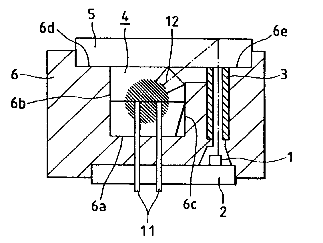
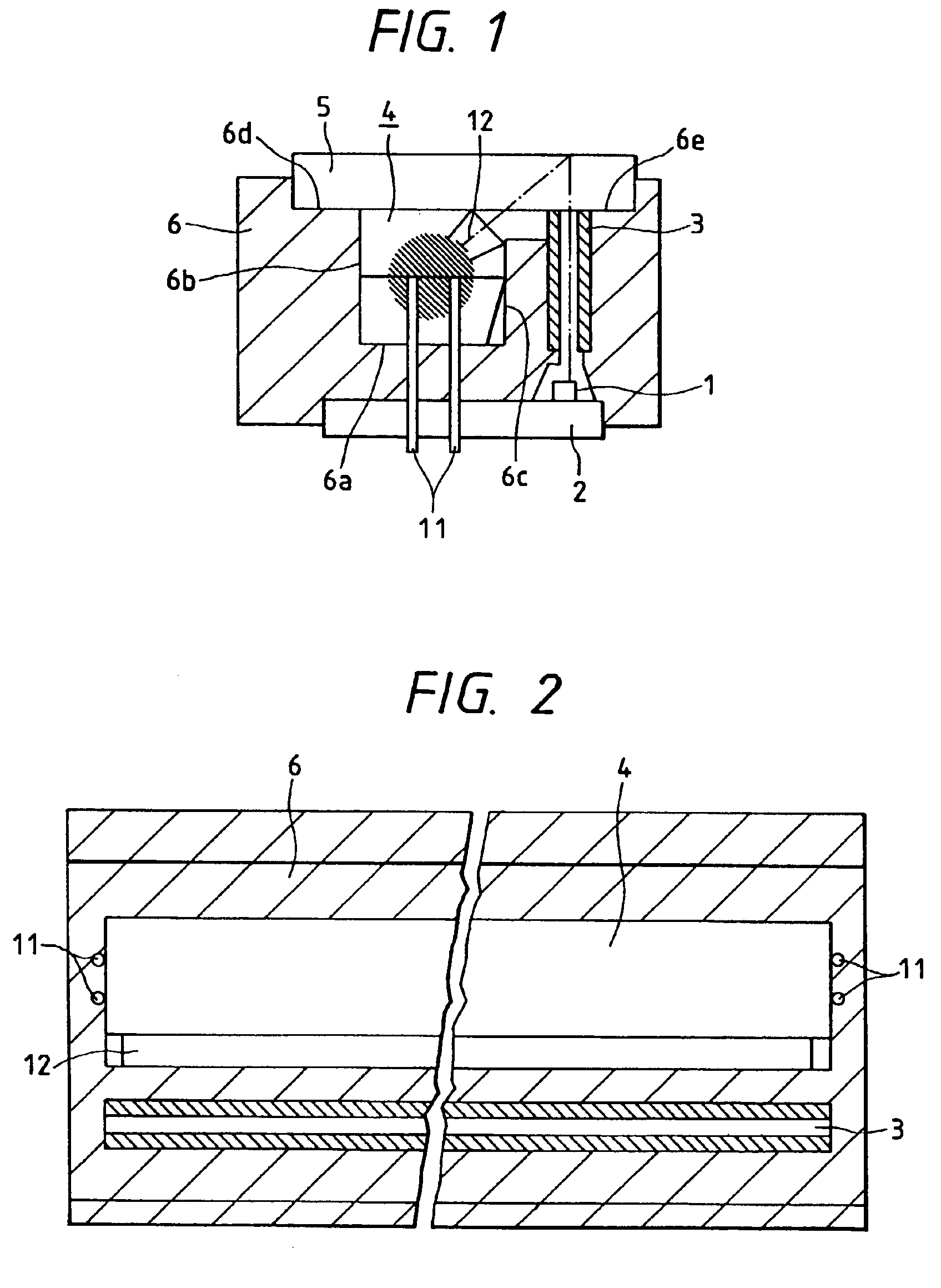
the invention will now be described hereinbelow with reference to FIGS. 1 to 5. FIG. 1 is a cross sectional view of an image reading apparatus and FIG. 2 is a top view thereof.

The image reading apparatus according to the present embodiment is constructed by: the image sensor board 2 in which a plurality of sensor ICs 1 each having a group of line-shaped photoelectric converting elements (line sensors) are accurately arranged on a board made of a glass epoxy material or the like in correspondence to a length of original to be read; the lens array 3 serving as an image forming optical system; the illuminating unit 4 serving as illuminating means; the cover glass 5 serving as supporting means for supporting an original and made of a light transmitting material; and the frame 6 serving as holding means and made of a material of a metal such as aluminum or the like or a resin such as polycarbonate or the like for positioning and holding the above component elements.

The original supported...


PUM


Abstract

There is disclosed an image reading apparatus constructed by an illuminating unit for illuminating an object in a line shape, an image forming optical system for forming a light, as an image, from the object illuminated by the illuminating unit, a line sensor for converting the light formed as an image by the image forming optical system into an image signal, and a frame for holding the illuminating unit and the line sensor, wherein a shape in which vertices of at least a part of the cross section of the illuminating unit are connected by straight lines is set to a polygon of a pentagon or more, so that an image can be stably read at a high quality.

Description

BACKGROUND OF THE INVENTION1. Field of the InventionThe invention relates to an image reading apparatus for reading an object image and outputting an image signal.2. Related Background ArtHitherto, as shown in a cross sectional view of FIG. 11, an image sensor which is in contact with an original to be read and reads an image is constructed by: an image sensor board 2 on which a sensor IC 1 is installed; a lens array 3 for guiding a reflected light from the original illuminated by an illuminating unit 4 to the sensor IC 1; a cover glass 5 which is come into contact with the original; and a frame 6 for positioning and holding those component elements.As an illuminating unit 4, a unit as shown in a cross sectional view and a top view of FIG. 12 is used. The illuminating unit 4 is constructed by: LEDs 7 of a lead frame type serving as light sources provided on both ends; an optical guide member 8 arranged in a longitudinal direction for converting a light irradiated from the LEDs into ...

Claims


Application Information

Patent Timeline
Patent Type & Authority Patents(United States)
IPC IPC(8): F21V8/00G03B27/54H04N1/028H04N1/04
CPCG02B6/0001G02B6/4298H04N1/02815H04N1/02835G02B6/0038G02B6/4201H04N2201/0241H04N2201/03112H04N2201/02414H04N2201/02435H04N2201/02449H04N2201/03125H04N2201/03129H04N2201/03141H04N2201/03145
Inventor TABATA, MASAMI
Owner CANON KK
Why Eureka
Try Eureka