

Liquid power machine
- Summary
- Abstract
- Description
- Claims
- Application Information
AI Technical Summary
Benefits of technology
Problems solved by technology
Method used
Image

Examples
Embodiment Construction
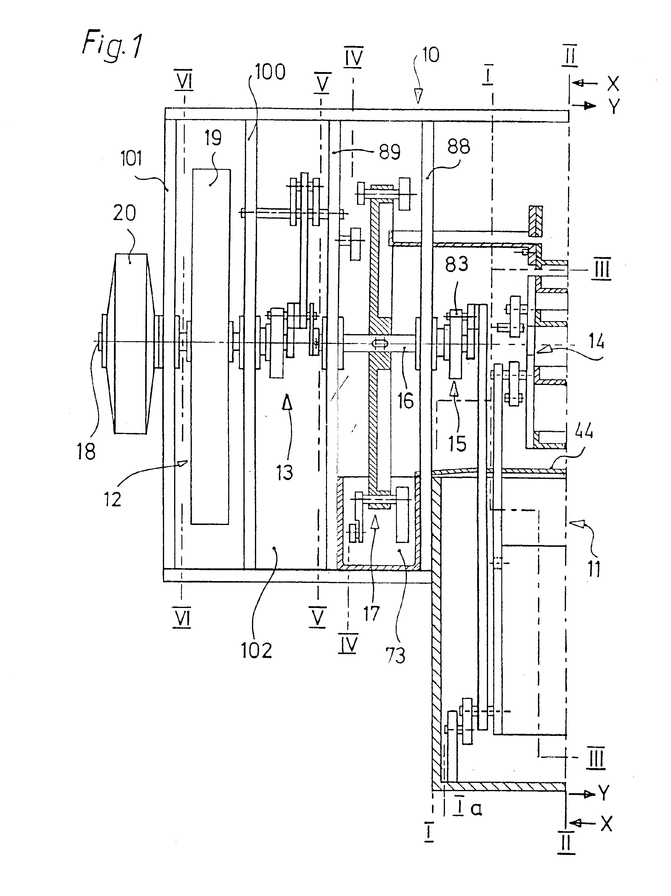
Referring to FIG. 1 the machine 10 includes a drive means indicated by reference 11 and a drive output means indicated by reference 12 which can be in engagement with each other by way of a lever drive assembly indicated generally at 13.
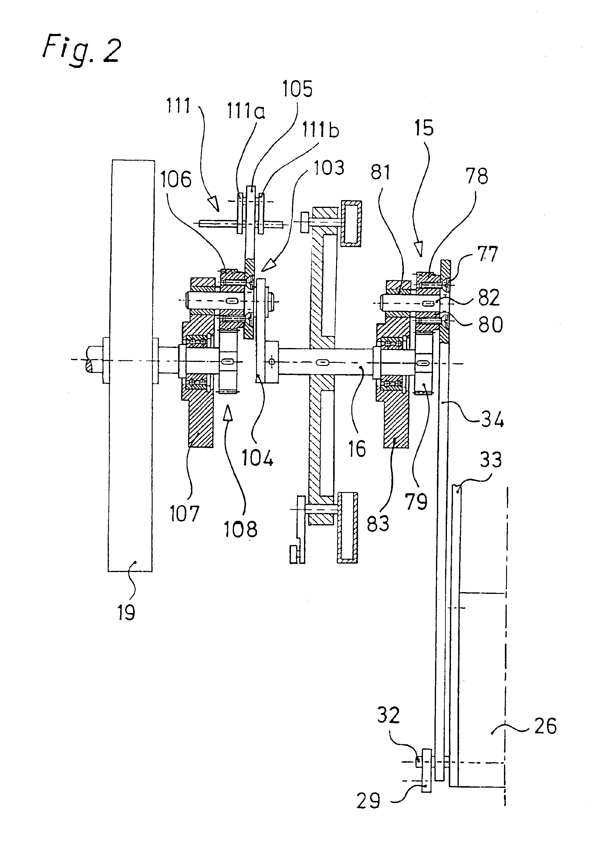
The drive means 11 substantially comprises a prime mover in the form of a hydraulic motor 14 (hereinafter referred to as the motor 14 for the sake of brevity) which is in engagement by way of a direction converter 15 with a first shaft 16 which in turn carries a wheel 90 of a conveyor arrangement 17. The drive output means 12 is substantially a second shaft 18 which as illustrated carries a flywheel 19 and which drives for example a current generator 20.
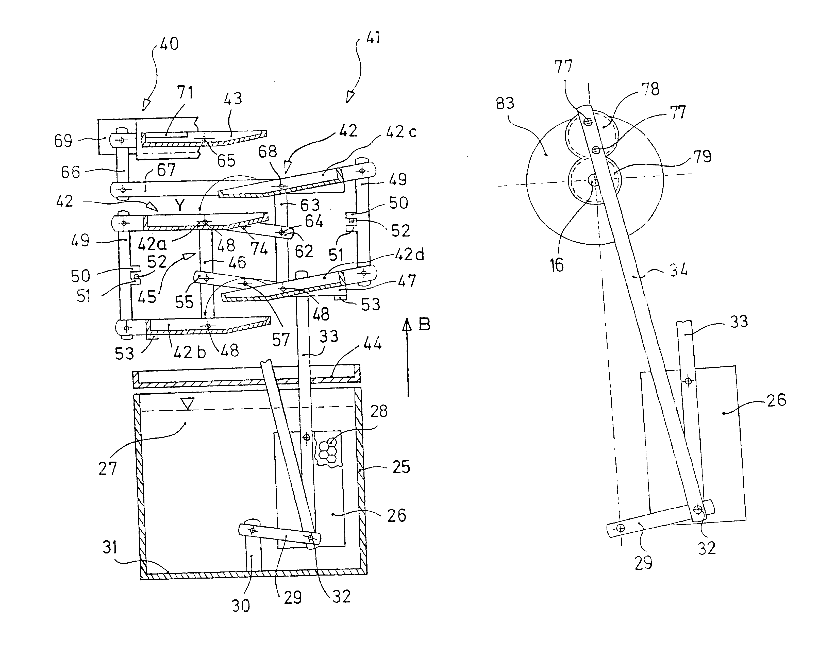
Referring to FIG. 4 showing a front view of the motor 14, the motor 14 comprises a liquid container 25 in which a buoyancy or float body 26 is accommodated, being immersed in a liquid 27 such as water and guided therein in such a way that it can move up and down. The float body 26 is a closed hollow b...
PUM
 Abstract
Description
Claims
Application Information