

Magnetic pole position detector for rotor
- Summary
- Abstract
- Description
- Claims
- Application Information
AI Technical Summary
Benefits of technology
Problems solved by technology
Method used
Image

Examples
second embodiment
this invention will be described referring to FIG. 7.
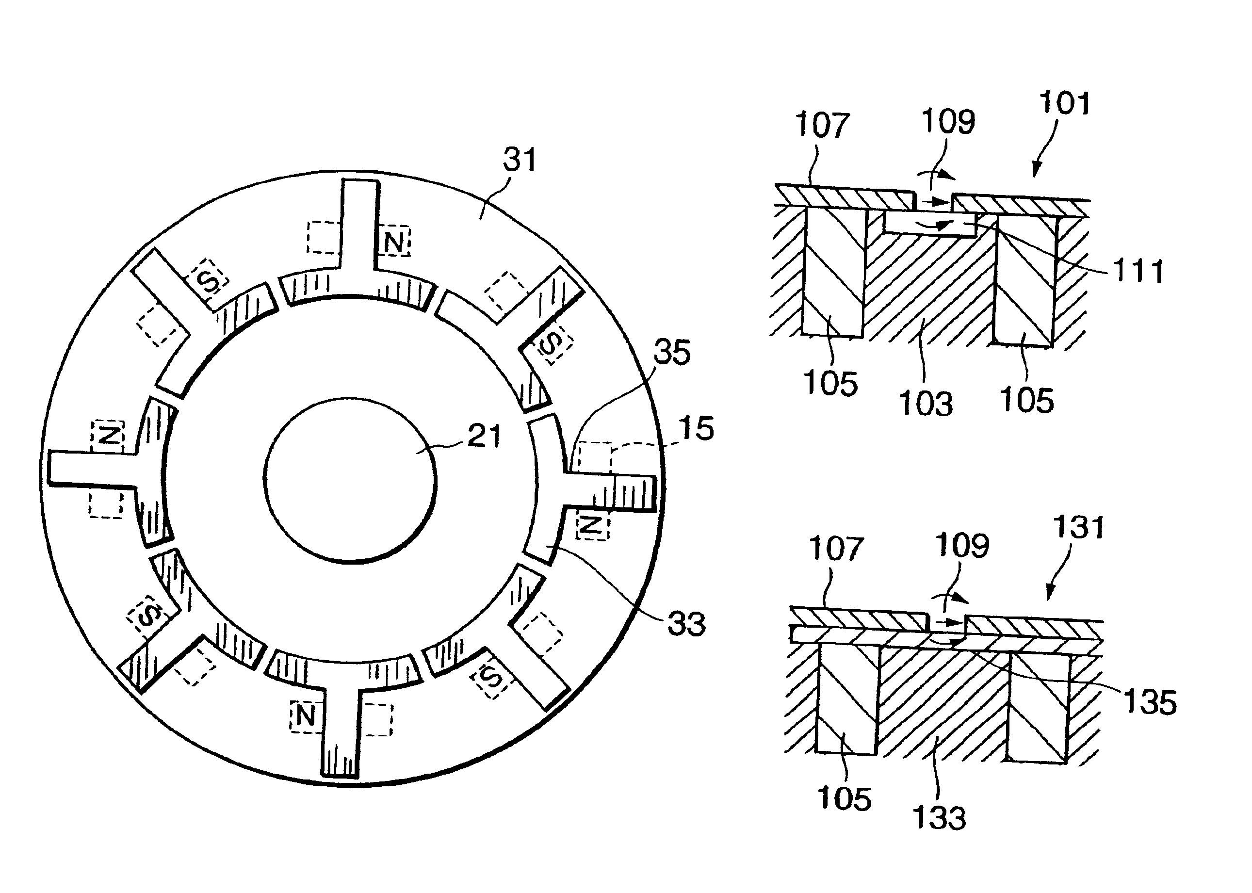
This embodiment differs from the first embodiment only with respect to the structure of the rotor. The rotor 31 in this embodiment is provided with plates 33 made of magnetic materials on an inner periphery of the axial end face. The plate 33 is formed in the shape of a letter “T”. The vertical section of the letter “T” reaches an outer periphery of the rotor in a radial direction.
This part functions as a magnetic passage 35 transmitting the magnetic flux of the magnet 15 to the plate 33. The horizontal section of the letter “T” is slightly arc-shaped. The distance between the horizontal section and the rotation shaft 21 is set shorter than the distance between the corresponding magnet 15 and the rotation shaft 21. The magnetic sensor is disposed to face a circular path on which the horizontal sections of the plates 33 travel.
Since this embodiment disposes the plates 33 at a position away from the stator, It is possible to reduce ...
fourth embodiment
this invention will be described with reference to FIG. 12.
This embodiment differs from the other embodiments with respect to the disposition of the magnets on the rotor. Specifically in this embodiment, pairs of two magnet components 210A, 210B of equal polarity are disposed on a rotor 201. Each pair of the magnet components 210A, 210B function as one magnet and the pairs of the magnet components 210A, 210B are disposed at fixed intervals. Plates 220 made of magnetic materials are disposed at positions corresponding to the respective pairs of the magnet components 210A, 210B on an axial end face of the rotor 201.
In all the rotors described earlier, the polarity of adjacent magnets was different. However it is possible to adapt this invention to the rotor 201 in which pairs of two magnet components 210A, 210B of equal polarity are provided to form a single magnetic pole.
According to this embodiment, the output signal of the magnetic sensor sharply varies when it passes a space betwe...
fifth embodiment
this invention will be described with reference to FIG. 13.
This embodiment relates to the shape of the plates made of magnetic materials.
The plates 25, 33, 63, 77, 107 and 220 used in the first to fourth embodiments are independent and are not in contact with each other. However in this embodiment, a disk 300 made of magnetic materials is divided into plate members 300A-300H by forming radial grooves on the disk 300. The plate members 300A-300H correspond to the single plates 25, 33, 63, 77, 107 and 220 in the first to fourth embodiments.
In this disk 300, the plate members 300A-300H are in electrical contact with each other at a central section of the disk 300. However the plate members 300A-300H still concentrate the magnetic flux on both sides of the grooves 301. This is achieved by disposing the magnets of the rotor such that each of the grooves corresponds to the central point of the space between two adjacent magnets. With such an arrangement, the single disk 300 may replace th...
PUM
 Abstract
Description
Claims
Application Information