Unit circuit, electronic circuit, electronic apparatus, electro-optic apparatus, driving method, and electronic equipment

a technology of electronic circuits and driving methods, applied in the direction of identification means, pulse techniques, instruments, etc., can solve the problems of display panels, difficult to make the characteristics of the driving transistor trb>1/b> uniform, and the variation of the gate voltage between the drain and the source with respect to the gate voltage of the driving transistor trb>1/b>, etc., to enhance the yield of electronic equipment and reduce the number of transistors to be used

Inactive Publication Date: 2005-02-22
ELEMENT CAPITAL COMMERCIAL CO PTE LTD
View PDF17 Cites 132 Cited by
  • Summary
  • Abstract
  • Description
  • Claims
  • Application Information

AI Technical Summary

Benefits of technology

Since the electronic equipment of the present invention has installed therein the electric circuit or the electro-optic apparatus, the threshold voltage of the driving transistor within the circuit can be c

Problems solved by technology

However, it is difficult to make the characteristics of the driving transistor Tr1 uniform over the pixels of the display panel due to various conditions, such as the properties and the thickness of semiconductor films, impurity concentration, diffusion areas, material properties and thickness of a gate insulating film, and the operating temperature.
When, in particular, a display panel is formed using the above-described circuits, variations in the electrical current characteristics between the

Method used


Image

  • Unit circuit, electronic circuit, electronic apparatus, electro-optic apparatus, driving method, and electronic equipment
  • Unit circuit, electronic circuit, electronic apparatus, electro-optic apparatus, driving method, and electronic equipment
  • Unit circuit, electronic circuit, electronic apparatus, electro-optic apparatus, driving method, and electronic equipment

Examples


first embodiment

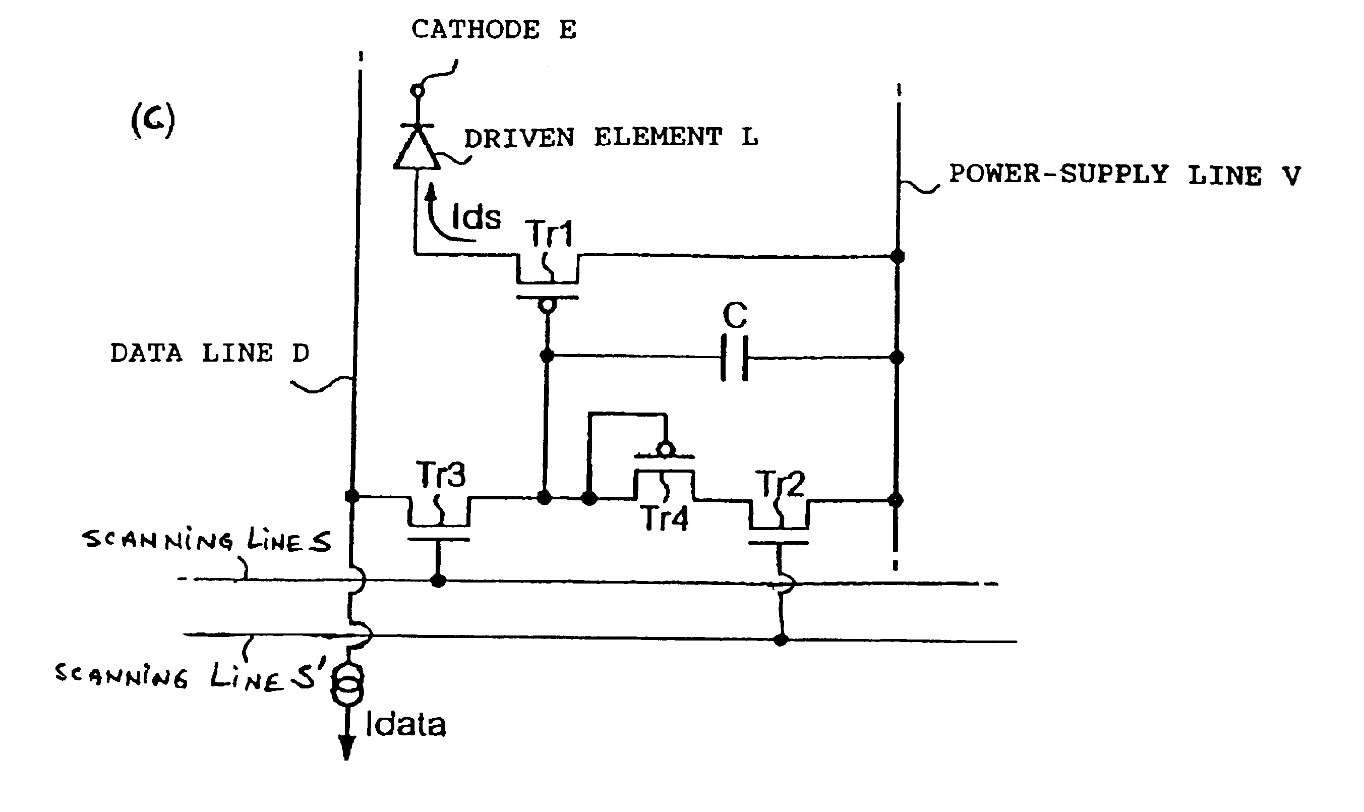
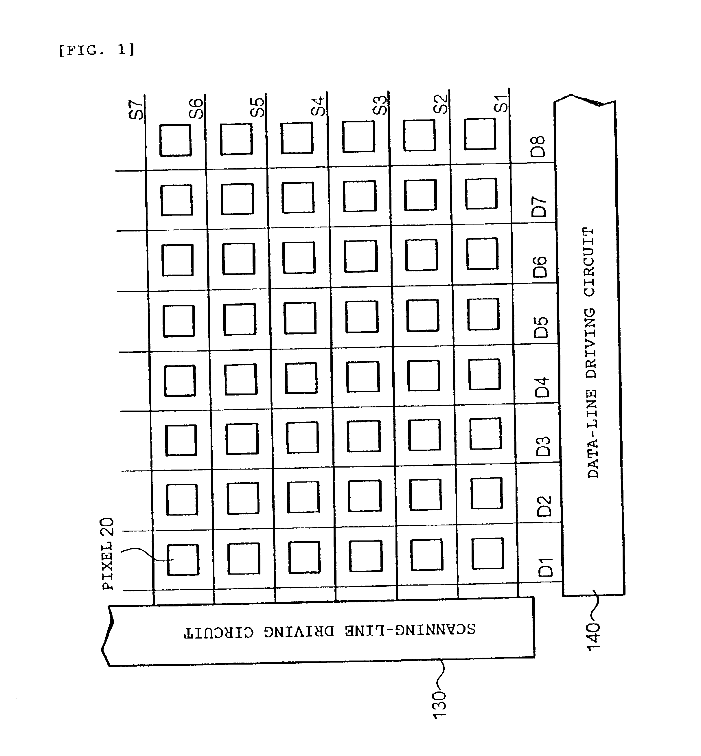
A first embodiment of the present invention will be described first. FIG. 1 shows the configuration of an electro-optic apparatus in which a unit circuit according to a first embodiment is used. As shown in FIG. 1, in this electro-optic apparatus, a plurality of scanning lines (S1, S2, S3, . . . ) and a plurality of data lines (D1, D2, D3, . . . ) are arranged so as to intersect each other, and a matrix of pixel circuits 20, which is an example of a unit circuit according to this embodiment, is provided, one at each intersection.

A scanning-line driving circuit 130 applies a selection electrical potential Vsel at a predetermined timing to each of the scanning lines S1, S2, S3, . . . A data-line driving circuit 140 applies data current Idata, each as a data signal, to the data lines D1, D2, D3, . . .

In FIG. 1, a power-supply line V (to be described below) is omitted. Furthermore, in this description, the portion where the pixel circuits 20 are arranged in a matrix is sometimes referre...

second embodiment

Application of Second Embodiment

In the display panel shown in FIG. 7, a description is provided by using an example in which gradation display using a single color is made for the sake of simplicity of description. However, when functioning as an actual display panel is considered, there are cases in which it is necessary to make a color display. Accordingly, an electro-optic apparatus for color display is described as an application example of the second embodiment.

FIG. 10 is a schematic showing a configuration of an electro-optic apparatus according to this application example. The electro-optic apparatus in FIG. 10 is an organic EL display using organic EL elements as electro-optic elements. Component members which are the same as those in FIG. 7 are given the same reference numerals, and detailed descriptions thereof are omitted.

In FIG. 10, the display-panel section 120 includes a red pixel circuit 200R having an organic EL element 210 which emits red light, a green pixel circui...


PUM


Abstract

The invention compensates for variations of a driving transistor Tr1. The invention provides a pixel circuit including a current-type driven element L, a driving transistor Tr1 to control the amount of electrical current to be supplied to the driven element, a capacitor element C connected to the gate of the driving transistor, a switching transistor Tr3 connected to the gate of the driving transistor, a switching transistor Tr1, a scanning line S connected to the gate of the switching transistor Tr3, a data line D connected to the source or the drain of the switching transistor Tr3, and a power-supply line V connected to a signal line via the switching transistor Tr3. A diode-connected compensating transistor Tr4 is disposed between the power-supply line V and the switching transistor Tr3.

Description

BACKGROUND OF THE INVENTION1. Field of InventionThe present invention relates to a unit circuit, an electronic circuit, an electro-optic apparatus, a driving method, and electronic equipment which can compensate for variations in the characteristics of transistors to drive current-type driven elements, such as organic electroluminescent elements.2. Description of Related ArtRecently, organic EL (electroluminescent) elements have attracted attention as becoming the next-generation light-emitting devices to replace conventional LCD (Liquid-Crystal Display) elements. Organic EL elements have excellent characteristics when used in display panels, for example, they are subject to a smaller dependence on the viewing angle because they are self-luminous, and they consume less power because they do not need a backlight or reflected light.Examples of a related art circuit to drive such an organic EL element include the configuration shown in FIG. 14. In this circuit, the drain of a driving t...

Claims


Application Information

Patent Timeline
IPC IPC(8): G09G5/00G09G3/10G09G3/28G09G3/04G09G3/30G09F9/30G09G3/20G09G3/32H01L29/786H01L29/66H03K17/695H05B33/02H05B33/14H05B33/08H01L51/50H01L27/32H05B44/00
CPCG09G3/3241G09G2300/0417G09G2300/0465G09G2300/0842H01L27/3244G09G2310/0262G09G2330/02G09G2330/021H01L27/3211G09G2310/0251H10K59/35H10K59/12G09G3/30
Inventor MIYAZAWA, TAKASHI
Owner ELEMENT CAPITAL COMMERCIAL CO PTE LTD
Why Eureka
Try Eureka