
Balanced programmable delay element

a programmable delay and element technology, applied in the field of delay lock loop (dll) applications, can solve the problems of inconsistency of delay line resolution, coarse resolution of delay line, and limitations of each type of delay line design

Inactive Publication Date: 2005-02-22
BROADCOM INT PTE LTD
View PDF4 Cites 39 Cited by
  • Summary
  • Abstract
  • Description
  • Claims
  • Application Information

AI Technical Summary

Benefits of technology

"The present invention provides a balanced programmable delay element with a variable incremental delay. The element includes two inverters and a current switch that receives control signals to selectively vary the delay. The technical effect of this invention is to provide a precise and programmable delay element for use in various electronic devices."

Problems solved by technology

Each of these types of delay line designs suffers limitations.
These limitations include the resolution of the delay of the delay line being too coarse, or the delay of the delay line being inconsistent.
Delay inconsistencies can be due to variations in the process used to fabricate the delay line, or variations in the delay of the delay line due to variations in the temperature or voltage supply of the delay line.
Unfortunately, in order to accommodate high frequency clock signals, the delay cells must feature a very small delay.
Another disadvantage of prior approaches is that the design often includes a plurality of parasitic capacitive elements in the signal path.
In these schemes, it is difficult to optimize the design of any one element since optimizing one element tends to diminish the performance of other elements in the signal path.
One difficulty with this approach is that the percentage of the fast clock is smaller than the same percentage of a slower clock (i.e., since the period of the fast clock is less than period of the slower clock, the same percentage of the period of the slower clock is larger than the period of the fast clock).
The use of delay elements having a single resolution is inefficient, since a slower clock can have a larger delay.
Unfortunately, the additional delay elements occupy more area, thereby increasing the cost of the part incorporating such a design.
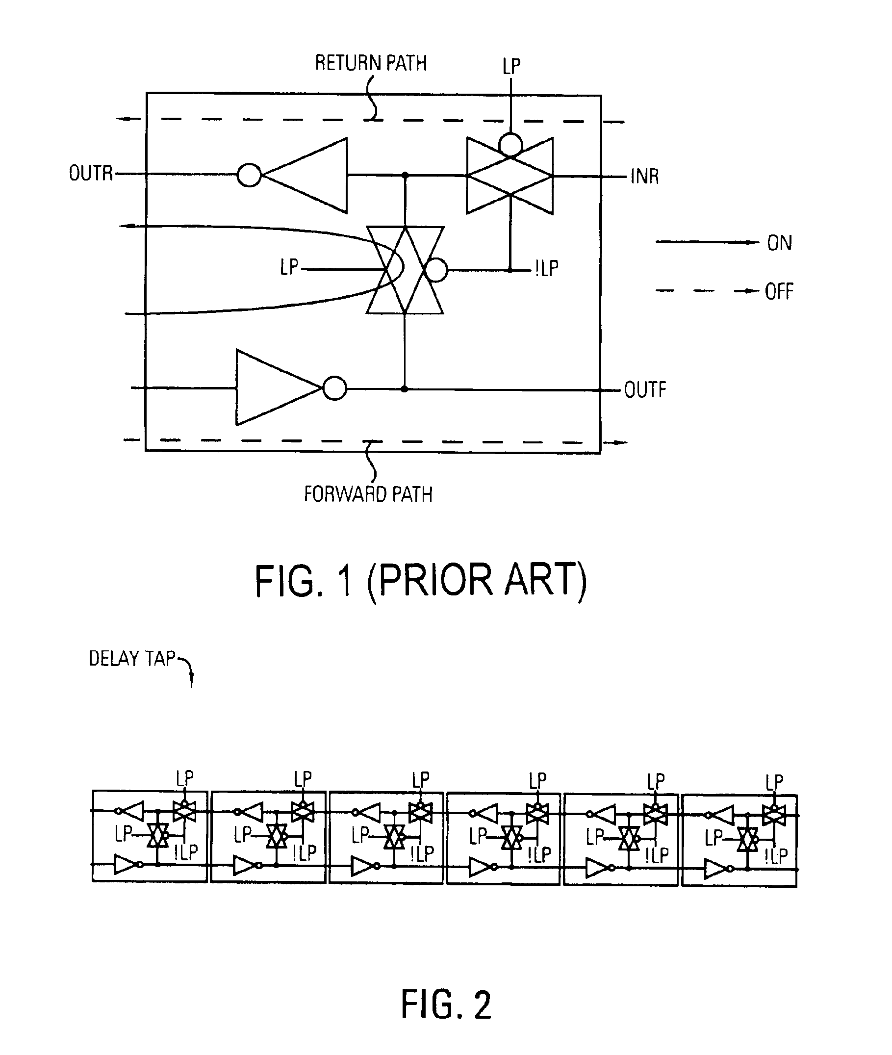
Another difficulty encountered by the prior art delay cell designs is that any errors in the design of the delay cell is compounded many times since there are typically seven to twenty delay cells per tap and 32 or 64 taps per delay chain.

Method used


Image

  • Balanced programmable delay element
  • Balanced programmable delay element
  • Balanced programmable delay element

Examples


Embodiment Construction

A balanced programmable delay element is described. In the following description, for the purposes of explanation, numerous specific details are set forth in order to provide a thorough understanding of the present invention. It will be apparent, however, to one skilled in the art that the present invention may be practiced without these specific details. In other instances, well-known structures and devices are shown in block diagram form in order to avoid unnecessarily obscuring the present invention.

Delay Cell 300

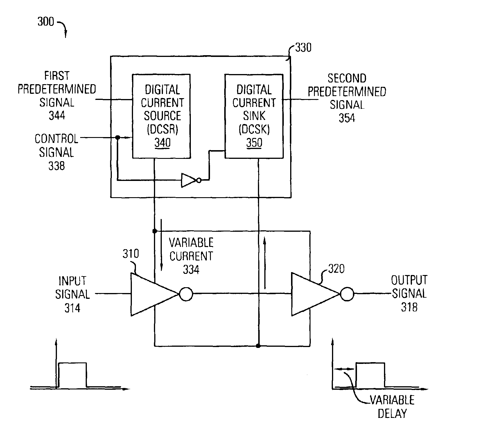
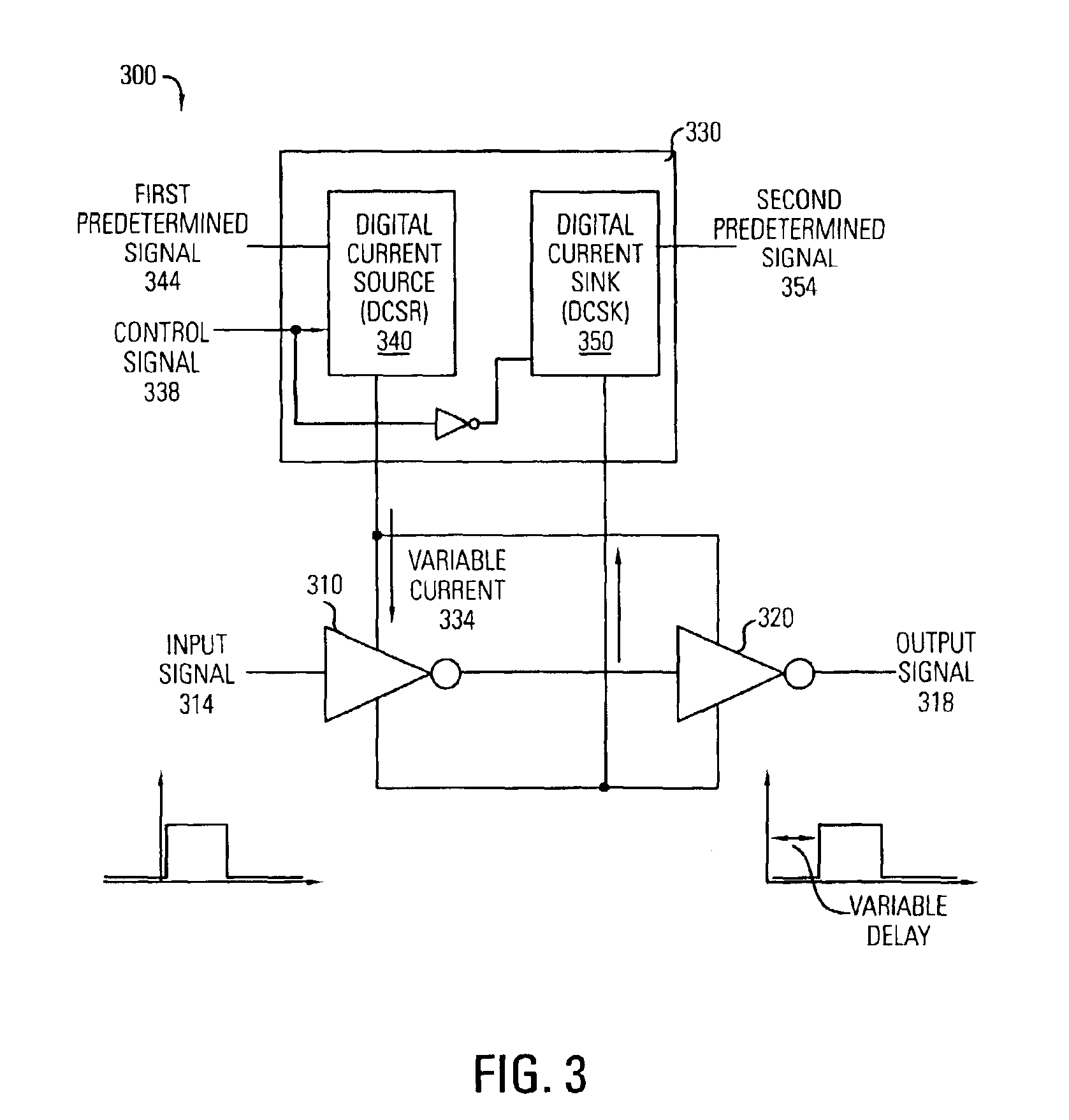
FIG. 3 illustrates a delay cell 300 according to one embodiment of the present invention. The delay cell 300 includes a first inverter 310 for receiving an input signal 314 and a second inverter 320 for generating an output signal 318. The input signal 314 can be, for example, an input clock signal as shown. It is noted that the output signal 318 is the input clock signal delayed by a variable delay 324.

The first inverter 310 and the second inverter 320 receive a variabl...


PUM


Abstract

Balanced programmable delay element that has a variable incremental delay. A first inverter is provided that has a first electrode for receiving an input signal, a second electrode, a third electrode, and a fourth electrode for providing an output signal and that has a propagation delay that is dependent on a first current. A second inverter is provided that has a first electrode coupled to the fourth electrode of the first inverter for receiving the output signal of the first inverter, a second electrode, a third electrode, and a fourth electrode for providing an output signal and that has a propagation delay that is dependent on a second current. A current switch is coupled to the first inverter, the second inverter, receives at least two control signals, and responsive thereto, selectively varies the incremental delay of the delay element.

Description

FIELD OF THE INVENTIONThe present invention relates generally to delay lock loop (DLL) applications, and more particularly, to a balanced programmable delay element for use in DLL applications.BACKGROUND OF THE INVENTIONIn many integrated circuit packages, it is desirable to provide a reference clock signal (also commonly referred to as a system clock). Many devices use the reference clock signal to derive their respective timing. For example, a reference clock signal may be provided to memory devices, processors, or other circuitry located on an integrated circuit (or chip).Often, it is desirable to delay the reference clock signal in a manner that creates multiple iterations of the clock signal. These multiple iterations of the reference clock are separated by a known period of time, which is commonly referred to as phase. For example, a known way of creating multiple iterations of a reference clock is to supply the reference clock to a delay locked loop (DLL). A DLL, as known in ...

Claims


Application Information

Patent Timeline
Patent Type & Authority Patents(United States)
IPC IPC(8): H03K5/13H03H11/26H03K5/04H03K17/687H03K5/00H03L7/081
CPCH03K5/133H03L7/0814H03K2005/00065H03L7/0818
Inventor TANG, HUAJUN
Owner BROADCOM INT PTE LTD
Learn More