
Test structure for measuring effect of trench isolation on oxide in a memory device

a memory device and trench isolation technology, applied in semiconductor/solid-state device testing/measurement, testing circuits, instruments, etc., can solve the problems of oxide edge degradation, sti damage at the edge, and sti damage is more severe, so as to achieve the effect of convenient implementation

Inactive Publication Date: 2005-02-22
MONTEREY RES LLC
View PDF16 Cites 7 Cited by
  • Summary
  • Abstract
  • Description
  • Claims
  • Application Information

AI Technical Summary

Benefits of technology

Embodiments of the present invention are drawn to providing an apparatus and method for measuring effects of isolation processes, e.g., shallow trench isolation, on oxide formation, e.g., tunnel oxide in a memory device, e.g., a flash memory device. Embodiments of the present invention further provide an apparatus to provide more comprehensive measurements related to oxide formation. Embodiments of the present invention further provide an apparatus which includes corner characteristics in measurements related to oxide formation. Embodiments of the present invention additionally provide an apparatus that obtains those measurement in a simple manner and which is readily implemented during the fabrication of a memory device.

Problems solved by technology

During the formation of STI, the silicon can be damaged at the STI corner (where the edges are compressed) and at the edge.
STI damage is more severe at the corner due to compressed edges causing crystal disruption and / or crystal dislocation.
This leads to imperfect tunnel oxide edge formation which can cause oxide edge degradation.
Oxide edge degradation is a contributing factor in reliability, charge retention, and leakage problems in memory devices.
However, in a practical application finger structures are not present.
Accordingly, edge measurements alone do not provide adequate information with regard to the formation of the oxide, e.g., tunnel oxide, in a memory device, e.g., a flash memory device.

Method used


Image

  • Test structure for measuring effect of trench isolation on oxide in a memory device
  • Test structure for measuring effect of trench isolation on oxide in a memory device
  • Test structure for measuring effect of trench isolation on oxide in a memory device

Examples


Embodiment Construction

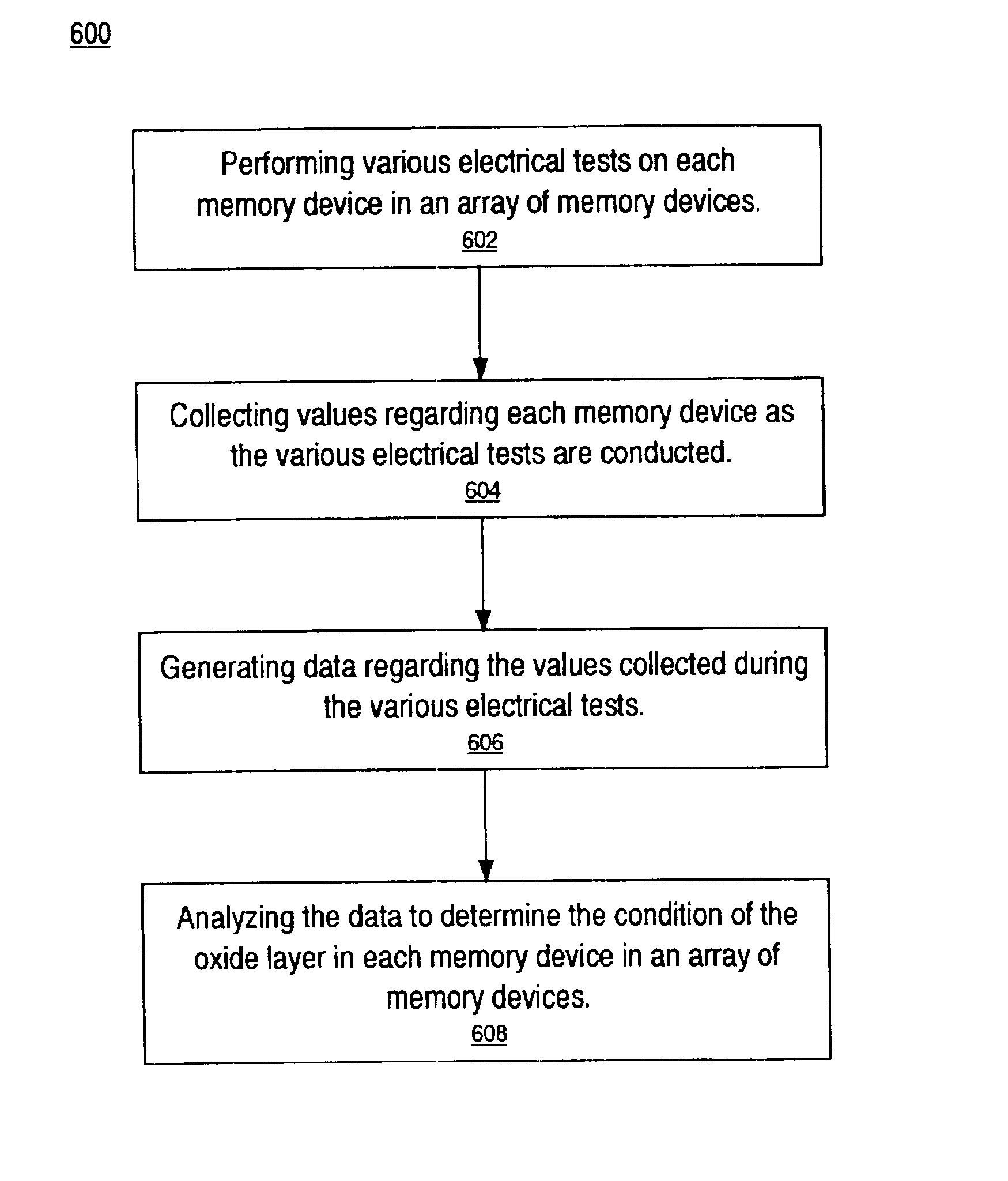
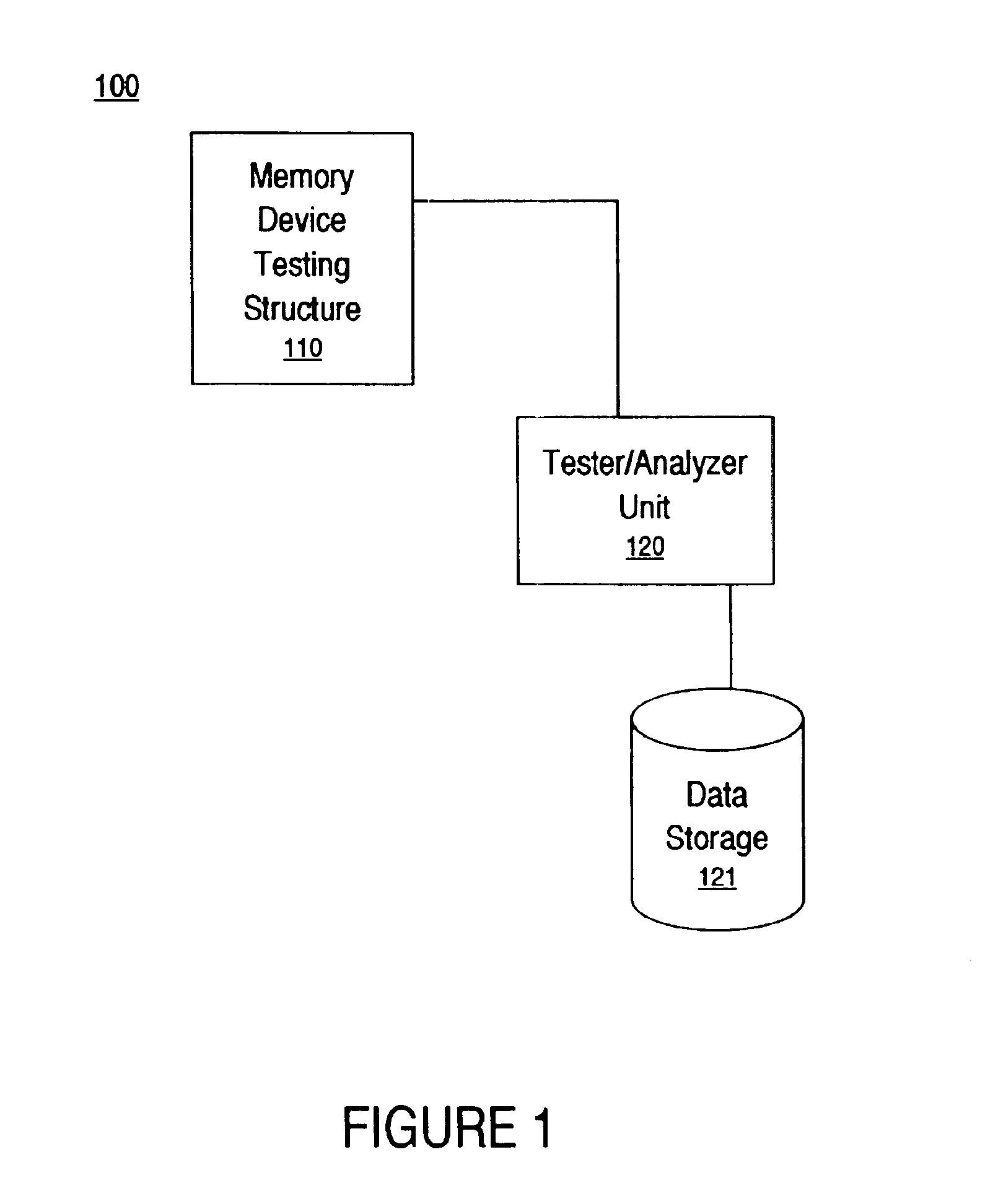
A method and apparatus for measuring effects of shallow trench isolation on oxide formation in a memory device. In the following description, for purposes of explanation, numerous specific details are set forth in order to provide a thorough understanding of the present invention. It will be obvious, however, to one skilled in the art that the present invention may be practiced without these specific details. In other instances, well-known structures and devices are shown in block diagram form in order to avoid obscuring the present invention.

Some portions of the detailed descriptions, which follow, are presented in terms of procedures, steps, logic blocks, processing, and other symbolic representations of operations performed on a memory device during fabrication. These descriptions and representations are the means used by those skilled in the fabrication arts to most effectively convey the substance of their work to others skilled in the art. A procedure, computer executed step, ...


PUM


Abstract

An apparatus for measuring effects of isolation processes (280) on an oxide layer (286) in a memory device (255) is described. In one embodiment, the apparatus comprises a structure (110) comprised of an array (110c) of memory devices (255). A testing unit (120) is coupled with the structure (110). The testing unit (120) is for performing various electrical tests on the array (110c) of memory devices (255). The testing unit (120) is also for providing data regarding each memory device (255) in the array (110c) of memory devices (255). An analyzer (120) is coupled with the structure (110) for analyzing results of the various electrical tests. This determines the condition of the oxide layer (286) of each memory device (255) in the array of memory devices (110c).

Description

FIELD OF THE INVENTIONThe present invention relates to measuring effects of processes performed upon oxides in memory devices. More particularly, the present invention relates to a testing structure for measuring edge and corner effects of shallow trench isolation on tunnel oxides in a flash memory device.BACKGROUND ARTAdvancements in technology and processes related to memory device fabrication have enabled continued scaling down (size reduction) of memory devices. As a memory device is scaled down, memory density is increased and the speed of the memory device is also increased. A contributory factor in the continuing scaling down of memory devices is the development of and introduction of STI (shallow trench isolation) into memory device fabrication.Implementing STI (shallow trench isolation) in memory device fabrication has enabled developers to properly scale down the memory device and improve circuit density. State of the art memory devices are being fabricated utilizing shall...

Claims


Application Information

Patent Timeline
IPC IPC(8): H01L23/544
CPCH01L22/34
Inventor YANG, NIANWANG, ZHIGANGYANG, TIEN-CHUN
Owner MONTEREY RES LLC
Features
  • Generate Ideas
  • Intellectual Property
  • Life Sciences
  • Materials
  • Tech Scout
  • Unparalleled Data Quality
  • Higher Quality Content
  • 60% Fewer Hallucinations
Learn More