Computer directed head stack assembly installation system

a technology of stack assembly and installation system, which is applied in the direction of electrical transducers, record information storage, instruments, etc., can solve the problems of read/write head crash, disc drive failure, and disc drive failur

Inactive Publication Date: 2005-03-01
SEAGATE TECH LLC
View PDF11 Cites 19 Cited by
  • Summary
  • Abstract
  • Description
  • Claims
  • Application Information

AI Technical Summary

Problems solved by technology

The slightest damage to the surface of a disc or read / write head can result in a catastrophic failure of the disc drive.
The primary causes of catastrophic failure, particularly read / write head crashes (a non-recoverable, catastrophic failure of the disc drive), are generally characterized as contamination, exposure to mechanically induced shock, and non-shock induced damage.
The source of non-shock induced damage is typically traced to the assembly process, and generally stems from handling damage sustained by the disc drive during the assembly process.
Part-to-part variation in critical functional attributes in the magnitude of a micro-inch can result in disc drive failures.
The aforementioned factors resultantly increase the difficulty of assembling disc drives.
As the assembly process becomes more difficult, the need to invent new tools, methods and control systems to deal with the emerging complexities presents unique problems in need of solutions.
Many of the tasks involved in modern assembly methods are beyond the capability of operators to reliably and repeatedly perform, further driving the need for automation equipment and tools.
The ability to assemble HDAs nominally free from the effects caused by unequal load forces on the read / write heads, disc pack imbalance or one of the components of runout, velocity and acceleration (commonly referred to as RVA) posses a significant challenge as track densities increase.
One cause of unequal load forces on the read / write heads stems from misalignment of the head stack assembly during assembly of the HDA.
Misalignment of the head stack assembly causes the fly-height of the individual read / write heads to deviate from optimum, causing an increase in the distance between the disc the head for some surfaces and decreasing the distance for others.
If the deviation is substantial, head / disc contact occurs that can lead to head crashes.
For less severe deviations in fly heights, soft read errors often develop.
If the soft errors are detected in the test process, the HDA is returned to the clean room for rework, exposing the HDA to handling damage.
If the soft errors go undetected during the test process and develop during operation in the field, disc drive performance denigrates, write faults may be reported and reliability of the disc drive suffers.
Errors are traceable to disc pack imbalance and RVA noise sources.
Even with improved approaches to the generation of position error signals in the disc drive servo system, the ability of the system to deal with such issues is finite.
An inability to accommodate changes in the disc drive attributes leads to field failures and an overall loss in product reliability, a detrimental impact to product market position.

Method used


Image

  • Computer directed head stack assembly installation system
  • Computer directed head stack assembly installation system
  • Computer directed head stack assembly installation system

Examples


Embodiment Construction

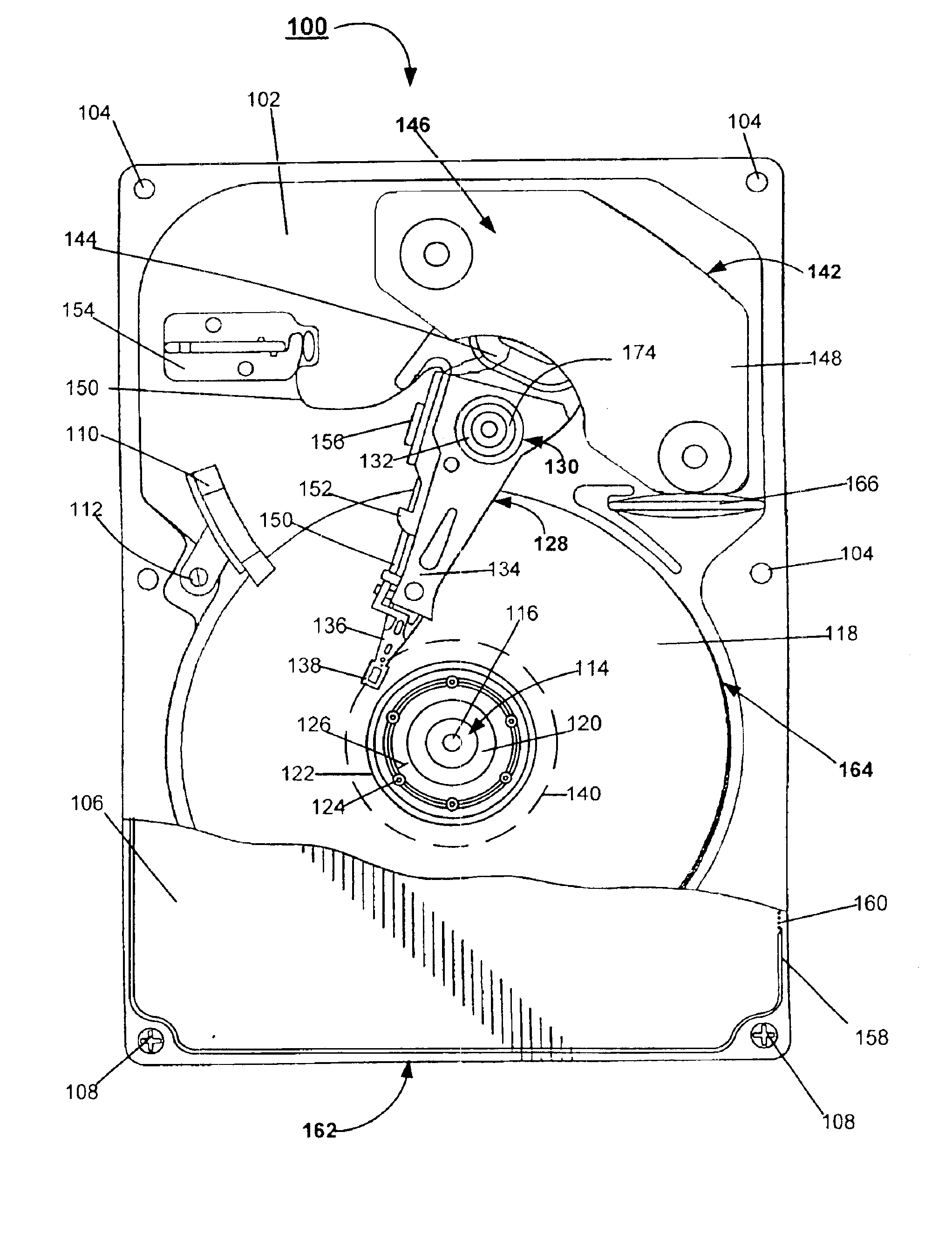
[0032]Referring to the draw in general, and more particularly to FIG. 1, shown therein is a top view of a disc drive 100 constructed in accordance with the present invention. The disc drive 100 includes a basedeck 102 that has several fastener receptacles 104, the basedeck 102 supporting various disc drive components, and a top cover 106 (shown in part), with several mounting apertures (not separately shown), secured to the basedeck 102 by top cover fasteners 108. The installed top cover 106 together with the basedeck 102 provides a sealed internal environment for the disc drive 100. Numerous details of and variations for the construction of the disc drive 100 are not included in the following description as such are well-known to those skilled in the art and are believed to be unnecessary for the purpose of describing the present invention.

[0033]Mounted to the basedeck 102 is a ramp load snubber assembly 110 secured to the basedeck 102 by a fastener 112, and a spindle motor 114 wit...


PUM

PropertyMeasurementUnit
distanceaaaaaaaaaa
mechanical resistanceaaaaaaaaaa
volatileaaaaaaaaaa

Abstract

The present invention provides a computer directed head stack assembly installation system with an installation software stored on recordable media directing the controlling a sequence of head stack installation assembly steps executed by a robotic assembly to pick and place a head stack assembly into a basedeck. The installation software program monitors compliance of the placement operation regarding mechanical resistance encountered by the head stack assembly engaging the basedeck compared to a dynamic force threshold F determined by the equation [F=(f(p)+ / −x)] and against the dynamic slope V determined by the equation [V=V=(fn−fn−1) / (pn−pn−1). Upon successful installation of the head stack assembly into the basedeck forming the head disc assembly, the head disc assembly is released from the head stack assembly installation station.

Description

RELATED APPLICATIONS[0002]This application claims priority to U.S. Provisional Application No. 60 / 150,138 filed Aug. 20, 1999.FIELD OF THE INVENTION[0003]The present invention relates generally to the field of disc drive data storage devices, and more particularly, but not by way of limitation, to a method for directing the automated manufacture of a disc drive head-disc assembly.BACKGROUND[0004]Modern hard disc drives are commonly used in a multitude of computer environments, ranging from super computers through notebook computers, to store large amounts of data in a form that can be made readily available to a user. Typically, a disc drive comprises one or more magnetic discs that are rotated by a spindle motor at a constant high speed. The surface of each disc is a data recording surface divided into a series of generally concentric recording tracks radially spaced across a band having an inner diameter and an outer diameter. The data tracks extend around the disc and store data ...

Claims


Application Information

Patent Timeline
Patent Type & Authority Patents(United States)
IPC IPC(8): G06F19/00
CPCG11B5/4813Y10T29/49025
Inventor SLIFE, RUSSELL P.JENKINS, JAMES R.JESSEN, ROGER A.FOWLER, RONALD D.
Owner SEAGATE TECH LLC
Why Eureka
Try Eureka