Wiper control

a technology of wiper blade and control panel, which is applied in the direction of dynamo-electric converter control, vehicle cleaning, instruments, etc., can solve the problems of affecting the performance of the wiper blade and the external object, and achieve the effect of preventing the increase of the noise level during the process of stopping the wiper blad

Inactive Publication Date: 2015-02-17
ROBERT BOSCH GMBH
View PDF13 Cites 20 Cited by
  • Summary
  • Abstract
  • Description
  • Claims
  • Application Information

AI Technical Summary

Benefits of technology

[0005]The object of the invention is to specify a method and a device for controlling the movement of a wiper blade across a surface, with which increased noise level during the process of stopping the wiper blade can be prevented.
[0008]If there is no reversing signal, then the wiper blade can be moved from the downward movement into a second park position and stopped there. The wiper blade can thus be removed from the wiping surface when the wiping movement is ended. Visual and aerodynamic advantages can result therefrom.
[0012]The mechanical resistance of the movement of the wiper blade can be determined on the basis of a current consumption of an electrical drive device driving the wiper blade. A dedicated sensor for recording the mechanical resistance can thus be avoided, enabling cost advantages to result.
[0013]Upon a request to move the wiper blade again after stopping, the wiper blade can first be moved upwards. Turning of the wiper lip prior to the actual wiping process can thus be avoided and a rapid start-up of the wiper blade across the wiping area is supported, so that a cleaning process can be set going more rapidly.

Problems solved by technology

If the wiper blade wipes across this area that is still moist during the stopping process, then the elastic stresses in the drive of the wiper blade will release suddenly, which can lead to striking through or impingement of the wiper blade on the external object.

Method used


Image

  • Wiper control
  • Wiper control
  • Wiper control

Examples


Embodiment Construction

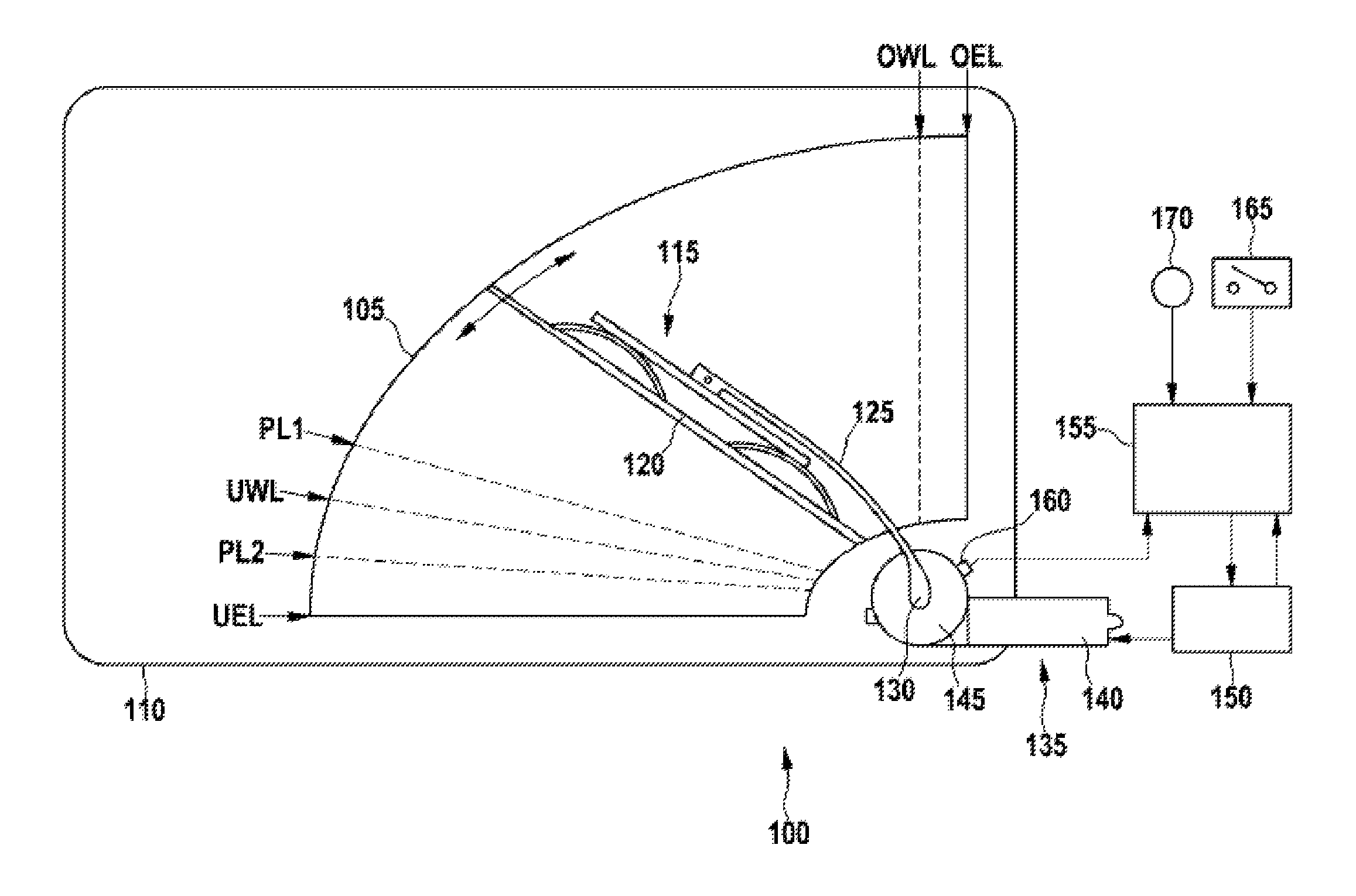
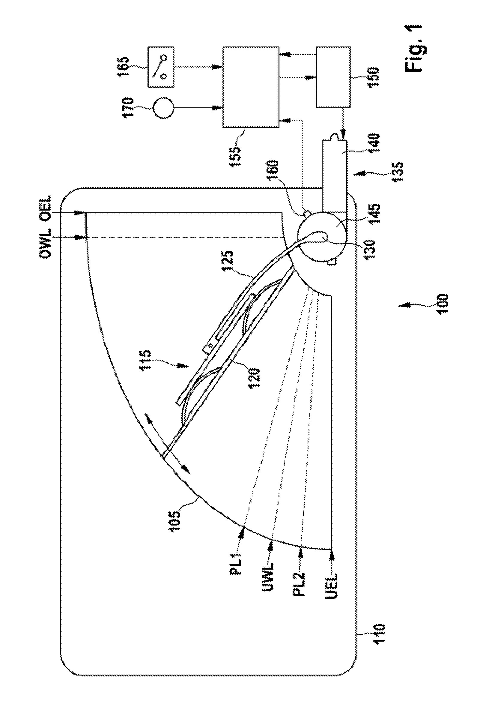
[0021]FIG. 1 shows a windscreen wiper system 100 for use on a motor vehicle. A wiping area 105 of a windscreen 110 essentially has the shape of a circular segment with an opening angle of approx. 90° . A wiper-blade 115 with a wiper lip 120 is attached to a wiper shaft 130 by means of a wiper arm 125, which shaft can be moved by a drive motor 135. The drive motor 135 comprises an electric motor 140 with a gearbox 145. The gearbox 145 usually comprises a reduction gearbox, and in another embodiment additionally or alternatively a coupling gear with a linkage.

[0022]The electric motor 140 is coupled to a circuit breaker 150. The circuit breaker 150 is connected to a processing means 155 and is controlled by it. Depending on control signals from the processing means 155, the circuit breaker 150 provides to the electric motor 140 one or more voltages, which can be influenced in respect of their frequency, phase and / or polarity. A current sensor integrated into the circuit breaker 150 pro...


PUM


Abstract

The invention relates to a method for controlling the movement of a wiper blade over a wiping surface, including the steps of moving the wiper blade up and down over the wiping surface between a lower turning position and an upper turning position, detecting a requirement to stop the wiper blade, moving the wiper blade downward into a lower end position and from there upward into a first parking position in the event that a reversing signal is present, and stopping the wiper blade. To this end, the wiper blade is moved into the lower end position only if previously thereto low mechanical resistance against the movement of the wiper blade over the wiping surface was determined.

Description

BACKGROUND OF THE INVENTION[0001]The invention relates to a method and a device for controlling the movement of a wiper blade over a surface.[0002]In order to rid a windscreen on a motor vehicle of contaminants and moisture, a wiper blade is moved across the screen in a reciprocal motion. For this purpose the wiper blade is usually mounted on a wiper arm, which is driven about a wiper shaft in an oscillatory motion. The wiper blade comprises a wiper lip, which rests on the windscreen and is pulled across it. The wiper lip is pulled by the wiper blade, so that for each change of direction of the wiper blade or the wiper arm, the wiper lip changes the side with which it is resting on the windscreen.[0003]In order to avoid the wiper lip becoming brittle on one side, the wiper blade is moved prior to the wiper system stopping, so that the wiper lip is brought into a predetermined placement position. The placement position can, for example, be changed periodically, either under timer con...

Claims


Application Information

Patent Timeline
Patent Type & Authority Patents(United States)
IPC IPC(8): G05B5/00H02P1/04H02H7/08B60S1/04B60S1/08
CPCB60S1/0896B60S1/08B60S1/0463
Inventor KARCHER, HUBERTUS
Owner ROBERT BOSCH GMBH
Why Eureka
Try Eureka