
Nut cap and assembly therewith

a technology of nut caps and nut caps, which is applied in the direction of threaded fasteners, mechanical equipment, transportation and packaging, etc., can solve the problems of cumbersome use, difficulty in secure, misplaced or lost, and two-part assemblies which are expensive to manufacture, and achieve easy use, secure holding, and low manufacturing cost

Inactive Publication Date: 2005-03-01
ILLINOIS TOOL WORKS INC
View PDF30 Cites 13 Cited by
  • Summary
  • Abstract
  • Description
  • Claims
  • Application Information

AI Technical Summary

Benefits of technology

A feature of the present invention is to provide a lug nut cover or cap which has only one part, which is inexpensive to manufacture and easy to use, and yet which also provides a very secure holding force on the vehicle lug nut.
Another feature of the present invention is to provide a capped wheel nut assembly which adds a simple modification to a standard wheel nut that cooperates with a feature on a snap-fitting lug nut cap to allow for a quick release of the cap from the nut.
Another feature of the present invention is to provide a lug nut cover which has a very secure holding force when assembled to an associated lug nut, but which is also easy to remove from the lug nut when removal is desired.
A further feature of this invention is to provide a capped wheel nut assembly which is rugged and durable in use and is capable of being inexpensively manufactured and assembled, and which can be quickly installed and removed from the wheel nut.

Problems solved by technology

However, one problem with these known covers is that it can be difficult to secure them to the vehicle lug nut and they are often misplaced or lost.
A number of patented caps have been developed to address this problem, such as found in U.S. Pat. Nos. 5,350,266 and 5,163,797, but these prior art patented caps have a two part assembly which is expensive to manufacture and which can be cumbersome to use.

Method used


Image

  • Nut cap and assembly therewith
  • Nut cap and assembly therewith

Examples


Embodiment Construction

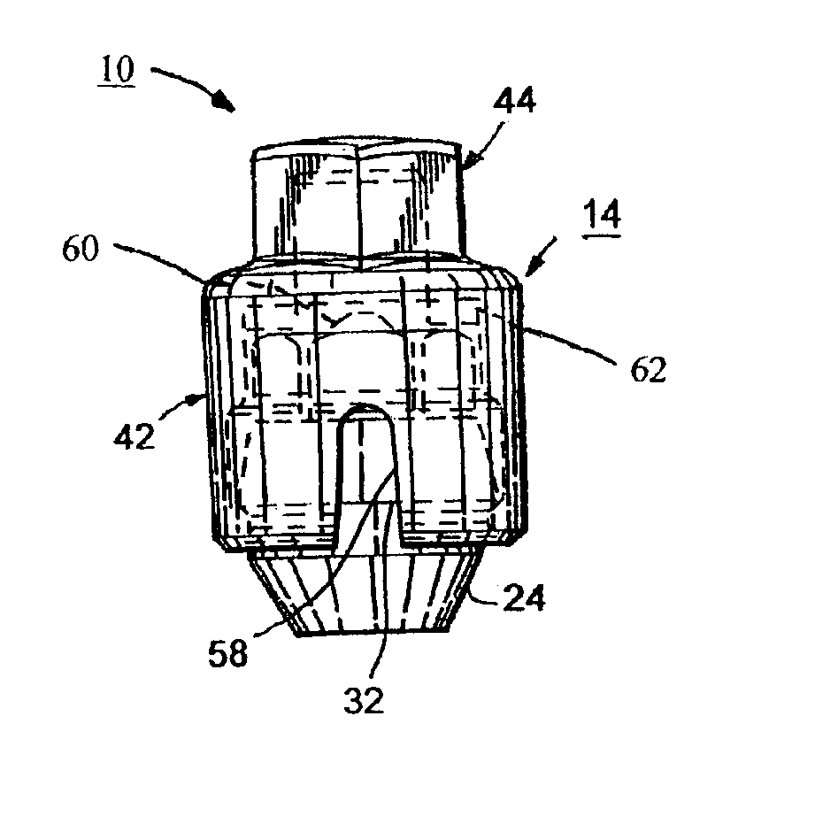
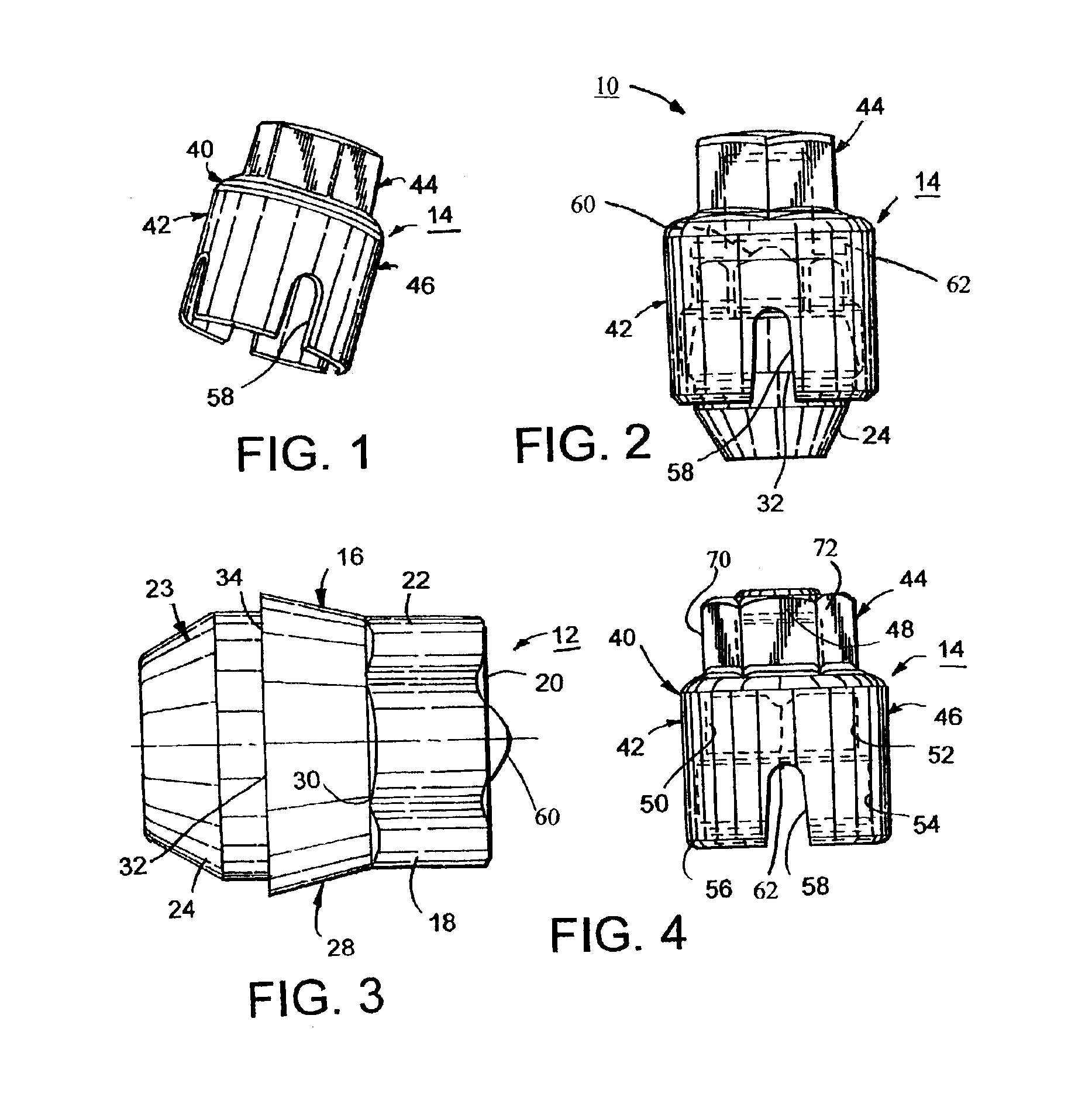
Referring to the figures, there is shown a capped wheel nut assembly 10 comprising a lug or wheel nut 12 and a cap 14 according to one embodiment of the present invention.

The wheel nut 12 is constructed in the form of an elongated tubular like body 16. The body 16 has a main body portion 18 extending from an end 20. The main body portion 18 has a polygonal side wall in the form of a six-sided regular polyhedron in which all six outer surfaces or flats 22 are identical and in which the angles between adjacent flats are all equal. The flats 22 extend parallel to the longitudinal center line of the tubular body 16. The tubular nut body 16 is tapered at the outer end 23 to provide a frusto-conical seat 24 adapted to engage a complementary mating surface. The nut body 16 is preferably interiorly threaded through the center of the nut body 16 as is commonly known. The nut body 16 has a collar member 28 between the main body portion 18 and the frusto-conical seat 24. The collar member 28 i...


PUM


Abstract

A nut cap and assembly therewith is provided. The capped nut assembly is made up of a nut body and a cap. The nut body has an elongated internally threaded member formed with polygonal side walls extending from a collar member at the inner end toward the outer end, and the cap has a hollow shell with an end wall closing one end and being open at an opposite end. The cap is sleeved over said nut body with its side wall surrounding the polygonal side walls and its closed end overlies the outer end of the nut body, and the open end of the cap has a radially inwardly flared resilient lip portion that attaches to the collar member in a snap fitting relationship. The outer end of the nut body has an engagement member protruding therefrom, and the inside surface of the hollow shell has a ramping member at a location that it is adapted to strike the engagement member whenever the cap is rotated about the nut body such that the ramping member biases the resilient lip portion in a direction to release its holding force on the collar portion.

Description

FIELD OF THE INVENTIONThis invention relates to capped nut assemblies, and more particularly, to capped wheel nut assemblies for automotive products.BACKGROUND AND SUMMARY OF THE INVENTIONLug nut covers are commonly used to protect the threads of the stud or lug bolt from damage, dirt and rust. However, one problem with these known covers is that it can be difficult to secure them to the vehicle lug nut and they are often misplaced or lost. A number of patented caps have been developed to address this problem, such as found in U.S. Pat. Nos. 5,350,266 and 5,163,797, but these prior art patented caps have a two part assembly which is expensive to manufacture and which can be cumbersome to use. Thus, there is a need for a new capped wheel nut assembly that addresses these problem and other problems associated with known designs.A feature of the present invention is to provide a lug nut cover or cap which has only one part, which is inexpensive to manufacture and easy to use, and yet w...

Claims


Application Information

Patent Timeline
IPC IPC(8): B60B7/00B60B7/06F16B37/14F16B37/00
CPCF16B37/14B60B7/00
Inventor VAN INGEN, JAMES M.WARD, MICHAEL L.
Owner ILLINOIS TOOL WORKS INC
Learn More