Control strategy for gas turbine engine

a technology for gas turbine engines and control systems, which is applied in the direction of machines/engines, engine starters, liquid fuel engines, etc., can solve the problems of increasing the limit on the inlet temperature of the turbine, consuming the lifetime of components, and producing larger thrust, so as to increase the limit on speed, consume the lifetime of the rotor and other components, and increase the limit. the effect of speed

Inactive Publication Date: 2005-03-01
GENERAL ELECTRIC CO
View PDF3 Cites 17 Cited by
  • Summary
  • Abstract
  • Description
  • Claims
  • Application Information

AI Technical Summary

Benefits of technology

For example, the invention may increase a limit on speed of a particular rotor, which consumes lifetime of the rotor and other components, but produces larger thrust presently. As another example, a limit on turbine inlet temperature may be raised, which again consumes lifetime of components, but produces larger thrust presently.

Problems solved by technology

As another example, a limit on turbine inlet temperature may be raised, which again consumes lifetime of components, but produces larger thrust presently.

Method used


Image

  • Control strategy for gas turbine engine
  • Control strategy for gas turbine engine
  • Control strategy for gas turbine engine

Examples


Embodiment Construction

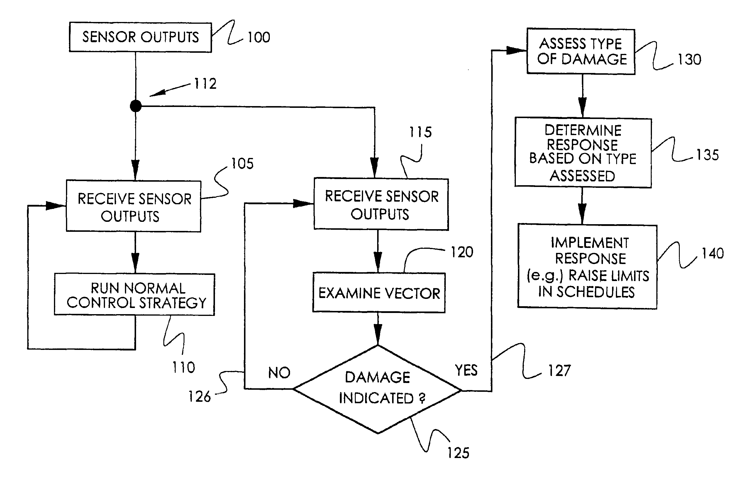
This discussion will present (1) a simplified example of one form of the invention, and then (2) a more general description.

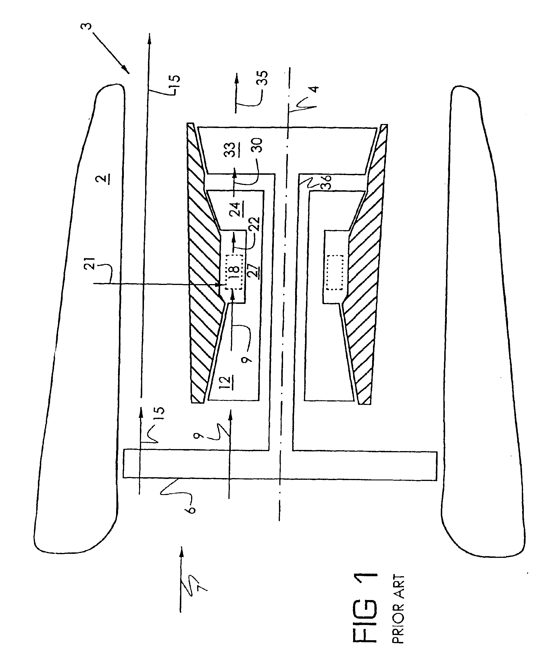
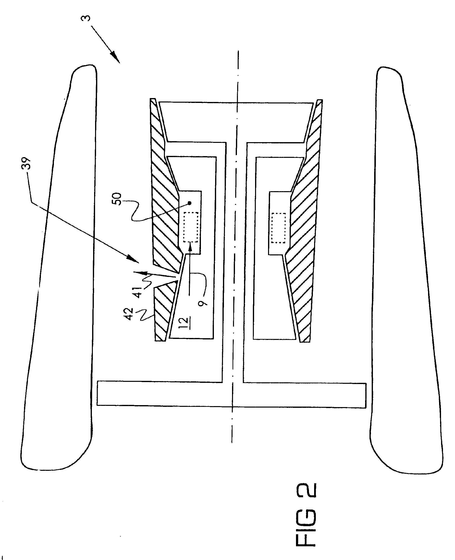
FIG. 1 illustrates a simplified gas turbine engine 3, which is symmetrical about centerline 4. A fan 6 compresses incoming air 7, and delivers part 9 to a high-pressure compressor 12. The other part 15 is bypassed, and used to generate thrust. The high-pressure compressor 12 further compresses the air, and delivers it to a combustor 18, wherein fuel 21 is delivered and burns, adding energy to the air in the form of heat.

The high-energy fuel / air mixture 22 is then ducted to a high-pressure turbine 24, which extracts mechanical energy from the mixture, and uses that energy to drive the high-pressure compressor 12, through shaft 27. The exhaust 30 of the high-pressure turbine 24 is ducted to a low-pressure turbine 33, which extracts further mechanical energy, and uses that energy to drive the fan 6, through shaft 36. The exhaust 35 of the low-pressure turbine 33 i...


PUM


Abstract

A control strategy for a gas turbine engine which exchanges future lifetime of the engine for present thrust. Gas turbine engines, such as those used in aircraft, sometimes incur damage, as when they ingest birds, or are struck with ballistic objects fired by an enemy. The invention detects the damage, and invokes a control strategy wherein the engine is operated in a more harsh manner, thereby sacrificing a significant part of the remaining lifetime of the engine, in order to obtain thrust currently.

Description

TECHNICAL FIELDThe invention concerns control systems for gas turbine engines.BACKGROUND OF THE INVENTIONIn a gas turbine engine used to power an aircraft, malfunctions sometimes occur. While many malfunctions are minor, some are significant enough to reduce thrust of the engine to a large degree. For example, if the engine ingests a large bird, damage can occur which significantly compromises the thrust-producing ability of the engine. As another example, a missile fired by a terrorist can produce similar damage, or worse. As a third example, during take-off, the engine can ingest debris left on a runway.In such cases, the pilot can take at least two strategies. One is to continue operation of the engine, but at the reduced thrust level. The second is to shut down the engine. The invention provides another strategy for operating a malfunctioning gas turbine engine.SUMMARY OF THE INVENTIONIn one form of the invention, a system detects damage in a gas turbine engine, as by detecting ...

Claims


Application Information

Patent Timeline
Patent Type & Authority Patents(United States)
IPC IPC(8): F01D21/00F01D21/14F02C9/28F02C9/00F02C9/46F02K1/15
CPCF01D21/14F02C9/28F02C9/46F05D2220/323F05D2270/12F05D2270/095F05D2270/051F05D2270/301F05D2270/044F05D2270/304
Inventor PISANO, ALAN DAVIDCONATY, JAMES PATRICKWISEMAN, MATTHEW WILLIAMSEQUEIRA, SABRINA ANNE
Owner GENERAL ELECTRIC CO
Why Eureka
Try Eureka