Golf shaft, forming method therefor and golf club

a forming method and golf shaft technology, applied in the field of golf shafts, can solve the problems of difficult to achieve ideal strength characteristics, unavoidably increased weight, and lack of depth or three-dimensional touch of the shaft, and achieve the effect of high crushing strength and high torsion strength

Inactive Publication Date: 2005-03-01
MAMIYA
View PDF13 Cites 25 Cited by
  • Summary
  • Abstract
  • Description
  • Claims
  • Application Information

AI Technical Summary

Benefits of technology

An object of the present invention is to provide a golf shaft which features lightness, high crushing strength and high torsion strength without interlayer peeling and has an aesthetically excellent design that gives users a sense of depth, and a method for forming the same and a golf club using the same.

Problems solved by technology

However, although a metallic color can be developed on the golf shaft surface by decoration techniques such as coating with metallic paints and evaporation, it does not give the shaft an appearance with a sense of depth or a three-dimensional touch.
However, in that case, the weight is unavoidably increased and ideal strength characteristics are difficult to achieve.
Usually metal wires have circular cross sections and, therefore, occupy a large proportion of the shaft thickness, so it is difficult to achieve ideal strength characteristics (particularly bending strength) in terms of a strength-to-weight ratio.
Besides, the weight of these metal wires is larger than carbon fiber.
The result is an increase in the overall weight of the golf shaft.
In addition, because metal wires have a poor adhesion and are easy to peel off, a larger volume of synthetic resin for bonding them must be used to prevent their peeling, leading to an increase in the overall weight of a golf shaft.

Method used


Image

  • Golf shaft, forming method therefor and golf club
  • Golf shaft, forming method therefor and golf club
  • Golf shaft, forming method therefor and golf club

Examples


Embodiment Construction

Next, preferred embodiments of the present invention will be described in detail referring to the attached drawings.

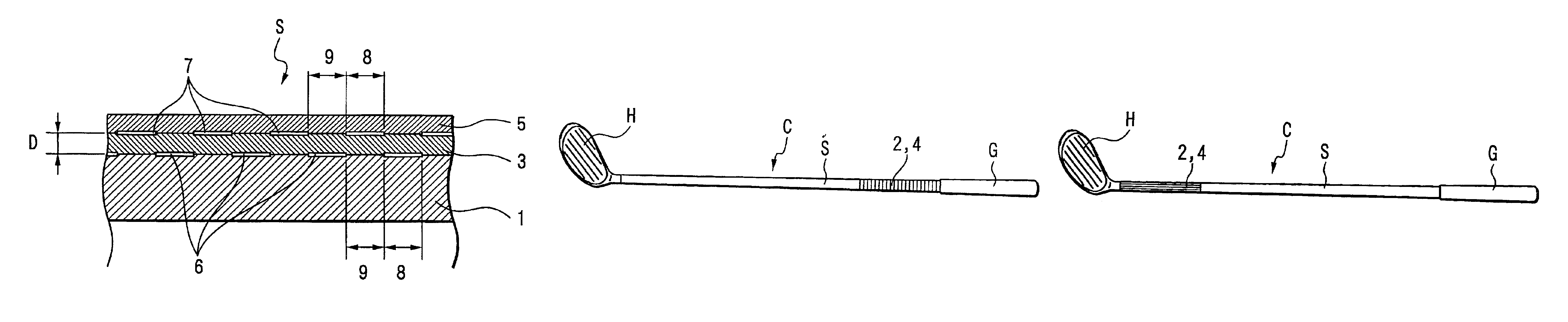
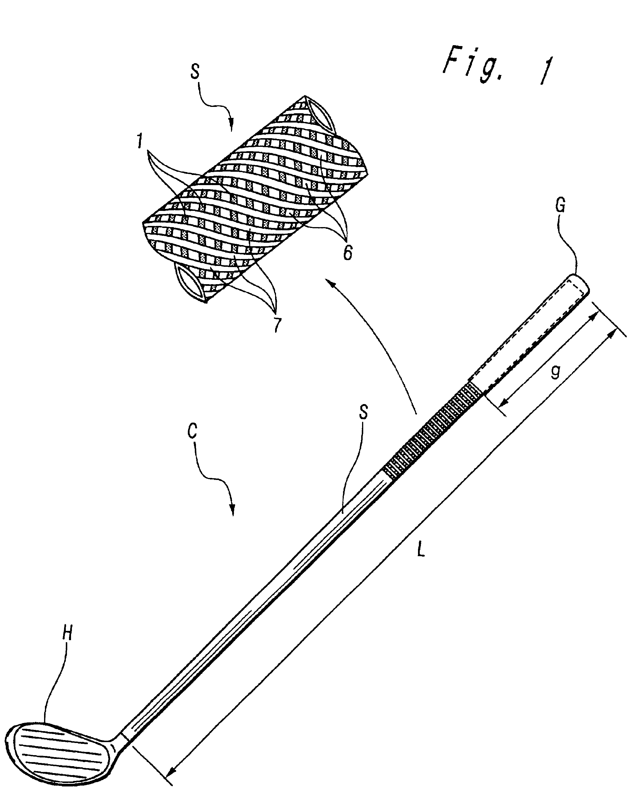
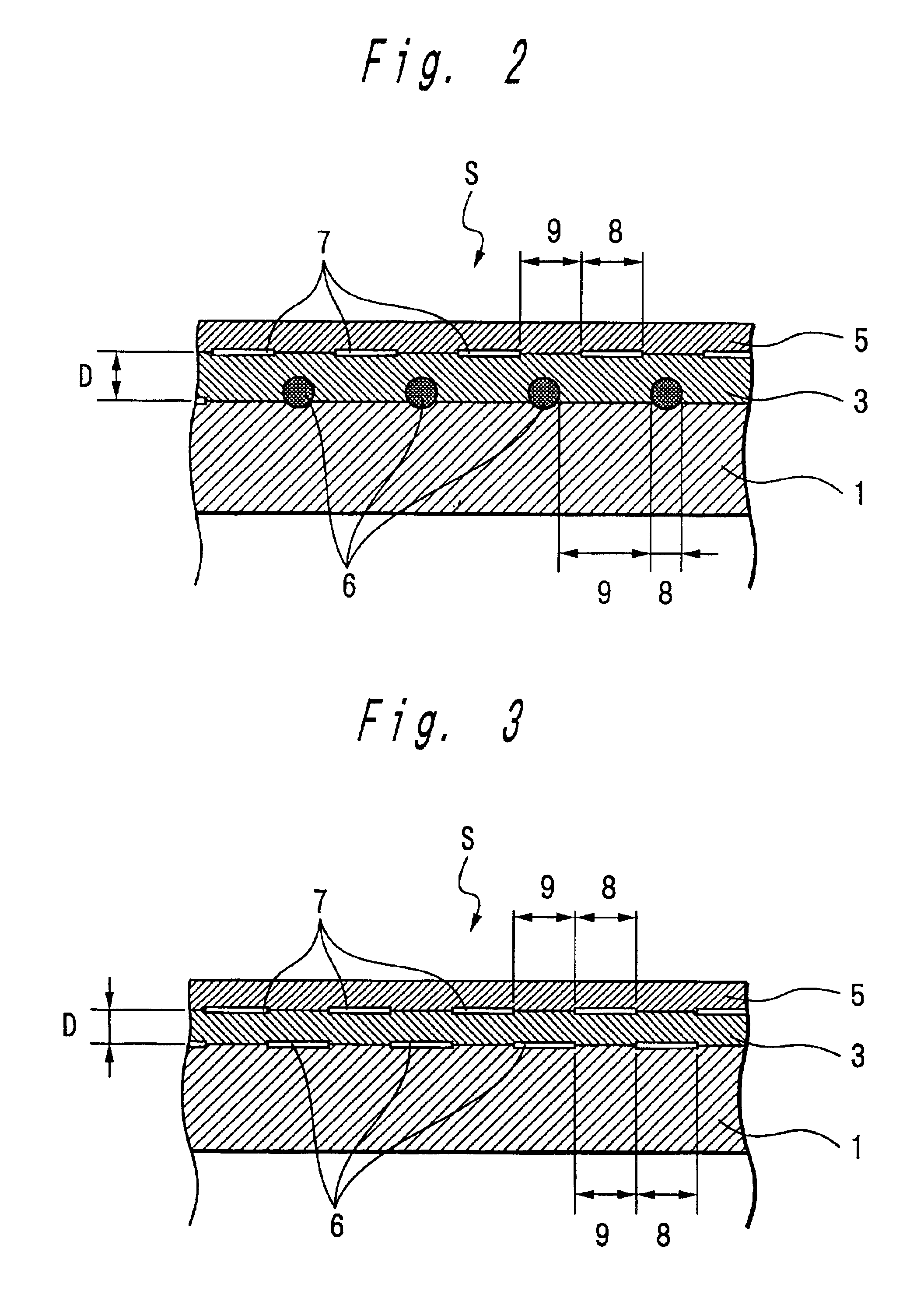
FIG. 1 shows a golf club C and, in enlarged form, part of the golf shaft S used in the golf club C according to one embodiment of the present invention. FIG. 2 is an enlarged sectional view showing the part of the golf shaft S shown in FIG. 1.

In this golf club C, a head H is set and bonded onto the smaller diameter end of a tapered golf shaft S and a grip G is fixed so as to cover an area away by a given distance from the larger diameter end.

The golf shaft S used in this golf club C is a laminate composed of a main layer 1 of high-strength high-elasticity fiber mainly impregnated with resin; metal wire layers 2 and 4 laid one upon the other over the main layer 1; and a low-elasticity fiber layer, laid over the metal wire layers, impregnated with resin through which the metal wire layers can be seen.

Typical materials which can be used for the high-strength, high-elastic...


PUM


Abstract

A golf shaft which features lightness, high crushing strength and high torsion strength with no interlayer peeling, as well as an excellent aesthetic design with a three-dimensional effect which gives the user a sense of depth, and a method for forming the same and a golf club using the same. The golf shaft is produced by baking a plurality of fiber prepreg layers. The shaft is a laminate comprising: a main layer of resin-impregnated high-strength high-elasticity fiber; a metal wire layer laid over the main layer; and a layer of low-elasticity fiber, laid over the metal wire layer, impregnated with resin through which the underlying metal wire layer can be seen.

Description

BACKGROUND OF THE INVENTION1. Field of the InventionThe present invention relates to a golf shaft, a forming method therefor and a golf club.2. Description of the Related ArtGenerally speaking, a golf shaft is made by the filament winding method in which filaments as resin-impregnated high-strength high-elasticity fiber are wound on a mandrel and baked, or by the sheet winding method in which a prepreg as a sheet composed of such filaments aligned is wound on a mandrel and baked, so it has some degree of flexibility and a high rigidity. Also, when carbon fiber is used as high-strength, high-elasticity fiber, a lightweight golf shaft with a high strength can be produced. A golf club which uses this type of golf shaft is used by many users.Regarding a golf shaft using carbon fiber, the flexural rigidity (bending strength), torsion strength, crushing strength and so on of a product (golf shaft) are considerably affected by the elasticity of the fiber used, the fiber's orientation with ...

Claims


Application Information

Patent Timeline
Patent Type & Authority Patents(United States)
IPC IPC(8): A63B53/10
CPCA63B53/10A63B2209/023A63B2209/02A63B59/0014A63B60/06A63B60/08A63B60/10
Inventor UNOSAWA, AKIRASOMENO, KAZUTAKA
Owner MAMIYA
Why Eureka
Try Eureka