Liquid crystal display

a liquid crystal display and display technology, applied in non-linear optics, instruments, optics, etc., can solve the problems of narrow viewing angle, decreased response speed, undesirable effects of ips-lcd on contrast ratio, etc., and achieve the effect of wide viewing angl

Inactive Publication Date: 2005-03-01
SAMSUNG DISPLAY CO LTD
View PDF34 Cites 19 Cited by
  • Summary
  • Abstract
  • Description
  • Claims
  • Application Information

AI Technical Summary

Benefits of technology

In the EOC-LCD according to the embodiments of the present invention, the liquid crystal molecules are symmetrically aligned to the surface which is equal distance from each of the electrodes. Accordingly, the phase retardation of the transmitted light is symmetrically caused, thereby obtaining a wide viewing angle.

Problems solved by technology

This type of TN-LCD unfortunately results in having a narrow viewing angle.
However, the IPS-LCD has undesirable effects of reduced contrast ratio due to light leakage in the dark state and the decreased response speed of the liquid crystal molecules.

Method used


Image

  • Liquid crystal display
  • Liquid crystal display
  • Liquid crystal display

Examples


example 1

The nematic liquid crystal having chiral dopant and the pure nematic liquid crystal were used as the liquid crystal layer 70, and the resulting viewing angles were measured for each case.

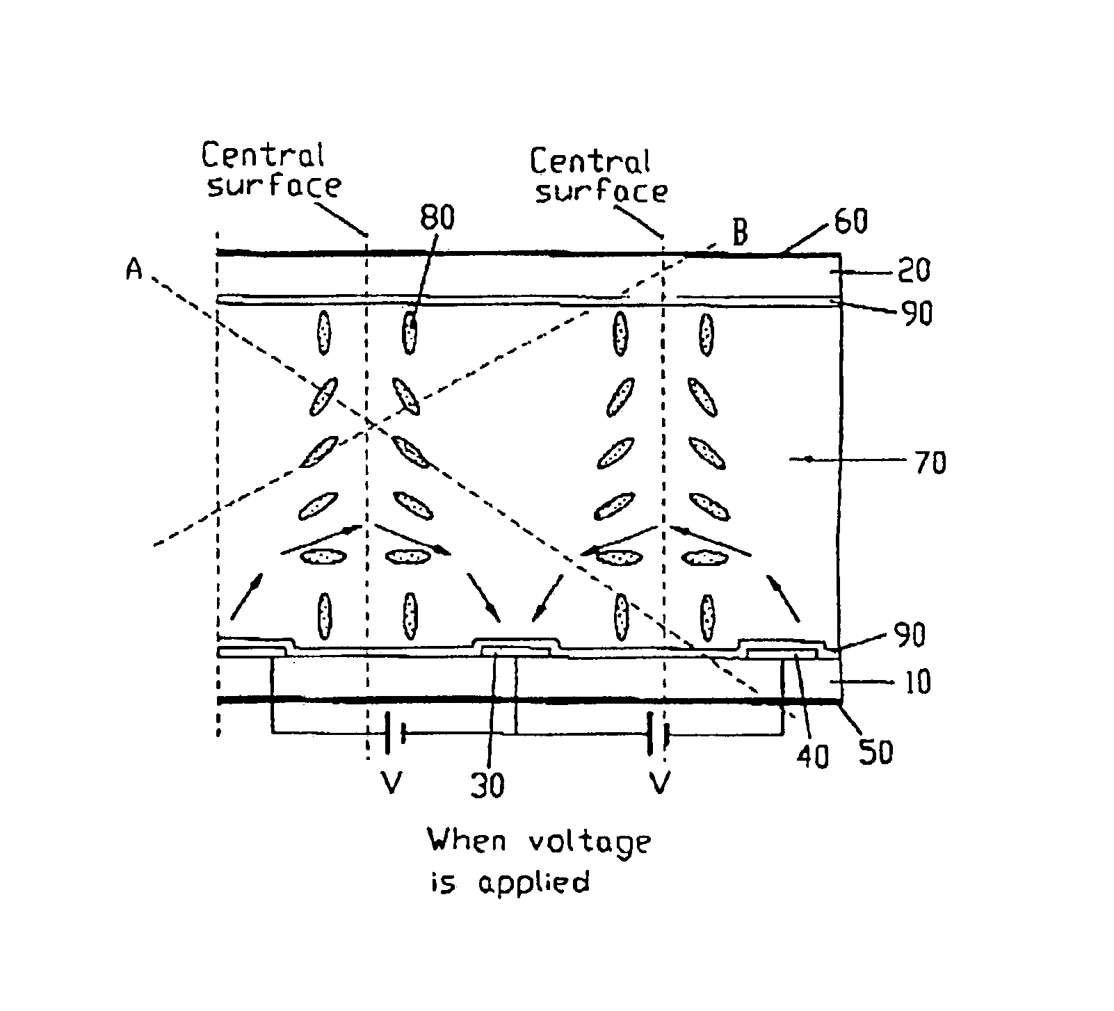
The refractive anisotropy n of the liquid crystal layer 70 was 0.09, the thickness d of the liquid crystal layer 70 was 4.5 μm, and the alignment films 90 were not rubbed. In addition, the two electrodes 30 and 40 were horizontally formed, and the transmission axes of the polarizing plates 50 and 60 attached to the outward surfaces of the two substrates 10 and 20 were formed to have an angle of 90° with respect to each other. The transmission axis of one polarizing plate were formed to have an angle of 45° with respect to the two electrodes 30 and 40, and the transmission axis of the other polarizing plate were formed to have an angle of 135° with respect to the two electrodes 30 and 40. The angles have been measured by setting the right side of the horizontal direction as zero degree.

FIG. 7 is a gr...

example 2

While maintaining the same condition as in example 1, the alignment films 90 formed on the two substrates 10 and 20 were rubbed, and the resulting viewing angles were measured in each case.

FIG. 9 is a graphical illustration of a viewing angle of the EOC-LCD obtained when the alignment film 90 formed on the upper substrate 20 was rubbed in the angle of 135° and when the alignment film 90 formed on the lower substrate 10 is rubbed in the angle of 315 °.

FIG. 10 is a graphical illustration of viewing angles of the EOC-LCD obtained when the alignment film 90 formed on the upper substrate 20 was rubbed in the angle of 45° and the alignment film 90 formed on the lower substrate 10 was rubbed in the angle of 225 °.

As shown in FIGS. 9 and 10, more uniform viewing angle can be obtained since the difference between the viewing angles in the horizontal and the vertical direction and the viewing angle in the diagonal direction can be reduced by rubbing the alignment films as described above.

example 3

While maintaining the same condition as in example 1, the viewing angle was measured by varying the orientations of the polarizing plates 50 and 60 attached to the outward surfaces of the two substrates 10 and 20.

FIG. 11 is a graphical illustration of viewing angles of the EOC-LCD obtained by arranging the transmission axis of the polarizing plates 60 attached to the outward surface of the upper substrates 20 to make an angle of 45° with respect to the direction of the two electrodes 30 and 40, and by arranging the transmission axis of the polarizing plate 50 attached to the lower substrate 10 to make an angle of 135° with respect to the direction of the two electrodes 30 and 40.

FIG. 12 is a graphical illustration of viewing angles of the EOC-LCD obtained by arranging the transmission axis of the polarizing plates 60 attached to the upper substrates 20 to make an angle of 30°, and by arranging the transmission axis of the polarizing plate 50 attached to the lower substrate 10 to mak...


PUM

PropertyMeasurementUnit
widthaaaaaaaaaa
widthaaaaaaaaaa
thicknessaaaaaaaaaa

Abstract

Two electrodes in parallel with each other are formed on one of two substrates, homeotropic alignment films are formed on the substrates and a liquid crystal material having positive dielectric anisotropy is injected between the substrates. When the voltage is applied to the two electrodes, a parabolic electric field between the electrodes drives the liquid crystal molecules. Since the electric field generated is symmetrical with respect to the boundary-plane equal distance from each of the two electrodes, the liquid crystal molecules are symmetrically aligned with respect to the boundary-plane. The electric field does not exert influences the liquid crystal molecules on the boundary-plane since the electric field on the boundary-plane is parallel with the substrates and perpendicular to the two electrodes; and thus, it is perpendicular to the liquid crystal molecules. Here, the polarization of the light is changed while passing through the liquid crystal layer and as a result, only a part of the light passes through the polarizing plate. The transmittance of the light can be varied by controlling the magnitude of voltage applied to the two electrodes.

Description

BACKGROUND OF THE INVENTION(a) Field of the InventionThe present invention relates to a liquid crystal display.(b) Description of the Related ArtGenerally, a conventional liquid crystal display (LCD) comprises two substrates having electrodes and liquid crystal injected therebetween. Light transmittance is adjusted by controlling the intensity of voltage being applied to the electrodes.Hereinafter, the conventional LCD is explained in detail with reference to the accompanying drawings.FIGS. 1A and 1B are sectional views of a conventional twisted-nematic liquid crystal display (TN-LCD). The TN-LCD in FIG. 1A, comprises: transparent glass substrates 1 and 2 facing each other; a liquid crystal layer 7 inserted between the substrates 1 and 2; and electrodes 3 and 4 formed respectively on the inner surfaces of the transparent glass substrates 1 and 2; and two polarizing plates 5 and 6 attached to the outer surface of the glass substrates 1 and 2 respectively for polarizing the light.The ...

Claims


Application Information

Patent Timeline
Patent Type & Authority Patents(United States)
IPC IPC(8): G02F1/13G02F1/1343G02F1/1337
CPCG02F1/134363G02F2001/133742G02F1/133742
Inventor SHIM, JUNG-UKKIM, KYEONG-HYEONKIM, NAM-HEUNGLEE, CHANG-HUNPARK, SEUNG-BEOM
Owner SAMSUNG DISPLAY CO LTD
Why Eureka
Try Eureka