Real image mode finder optical system

a technology of optical system and finder, which is applied in the field of real image mode finder optical system, can solve the problems of reducing the transmittance of the lens, increasing flare, and increasing the diameter of the front lens, so as to achieve compactness and increase the angle of emergence

Inactive Publication Date: 2005-03-01
OLYMPUS CORP
View PDF9 Cites 2 Cited by
  • Summary
  • Abstract
  • Description
  • Claims
  • Application Information

AI Technical Summary

Benefits of technology

It is, therefore, an object of the present invention to provide a real image mode finder optical system in which the angle of emergence can be increased and compactness can be attained.

Problems solved by technology

The virtual image mode finder has the advantage that an image erecting optical system is not required, but has the disadvantage that since an entrance pupil is located at the same position as an observer's pupil, the diameter of a front lens must be increased or the area of a visual field is not defined.
An Albada finder of this type allows the area of the visual field to be definitely set, but has the problem that a half mirror coating is applied to the surface of a lens and thus the transmittance of the lens is reduced or flare is increased.
A conventional real image mode finder, however, dose not provide a sufficient angle of apparent visual field (hereinafter referred to as an angle of emergence).
Thus, when the object is a person, there is the problem that it is difficult to view the expression of the person.
However, even such a finder does not provide a sufficiently large angle of emergence.
However, the telescope, which has a high magnification, namely a small angle of visual field, cannot be applied to a finder constructed to be independent of the photographing optical system, used in a common lens shutter camera which has a wide angle of view.

Method used


Image

  • Real image mode finder optical system
  • Real image mode finder optical system
  • Real image mode finder optical system

Examples


fifth embodiment

In the real image mode finder optical system of this embodiment, as shown in FIGS. 21A-21C, the objective optical system includes, in order from the object side, the first unit G1 with a negative refracting power, the second unit G2 with a positive refracting power, the third unit G3 with a negative refracting power, and a fourth unit G4 with a positive refracting power, and has a positive refracting power as a whole.

The fourth unit G4 is constructed with two prisms P1 and P2. The eyepiece optical system is constructed with the negative lens L1 and the positive lens E1 and has a positive refracting power as a whole.

The image erecting means includes the prisms P1 and P2. In the real image mode finder optical system of the fifth embodiment, the intermediate image formed by the objective optical system is interposed between the prism P2 and the negative lens L1, and the field frame, such as that shown in FIG. 4, is placed in the proximity of its imaging position.

The magnification of th...

sixth embodiment

The arrangement of this embodiment is similar to that of the first embodiment described with reference to FIGS. 1-4. FIGS. 25A-25D show the arrangement of the sixth embodiment. In this embodiment, low-dispersion glass is used for the positive lens E1 to suppress chromatic aberration of magnification produced in the eyepiece optical system.

Also, aberration characteristics in the sixth embodiment are shown in FIGS. 26A-26D, 27A-27D, 28A-28D, and 29A-29D.

Subsequently, numerical data of optical members constituting the real image mode finder optical system according to the sixth embodiment are shown below.

Numerical data 6Wide-angle positionMiddle positionTelephoto positionm 0.743 1.016 2.072ω (°)23.85417.511 8.739f (mm)11.15615.25231.104Pupil dia. (mm) 4.000r1 = 81.9112d1 = 1.0000nd1 = 1.58423νd1 = 30.49r2 = 10.0742 (aspherical)d2 = D2 (variable)r3 = 10.3535 (aspherical)d3 = 4.3238nd3 = 1.52542νd3 = 55.78r4 = −20.9984 (aspherical)d4 = D4 (variable)r5 = −10.0333 (aspherical)d5 = 1.0000nd...

seventh embodiment

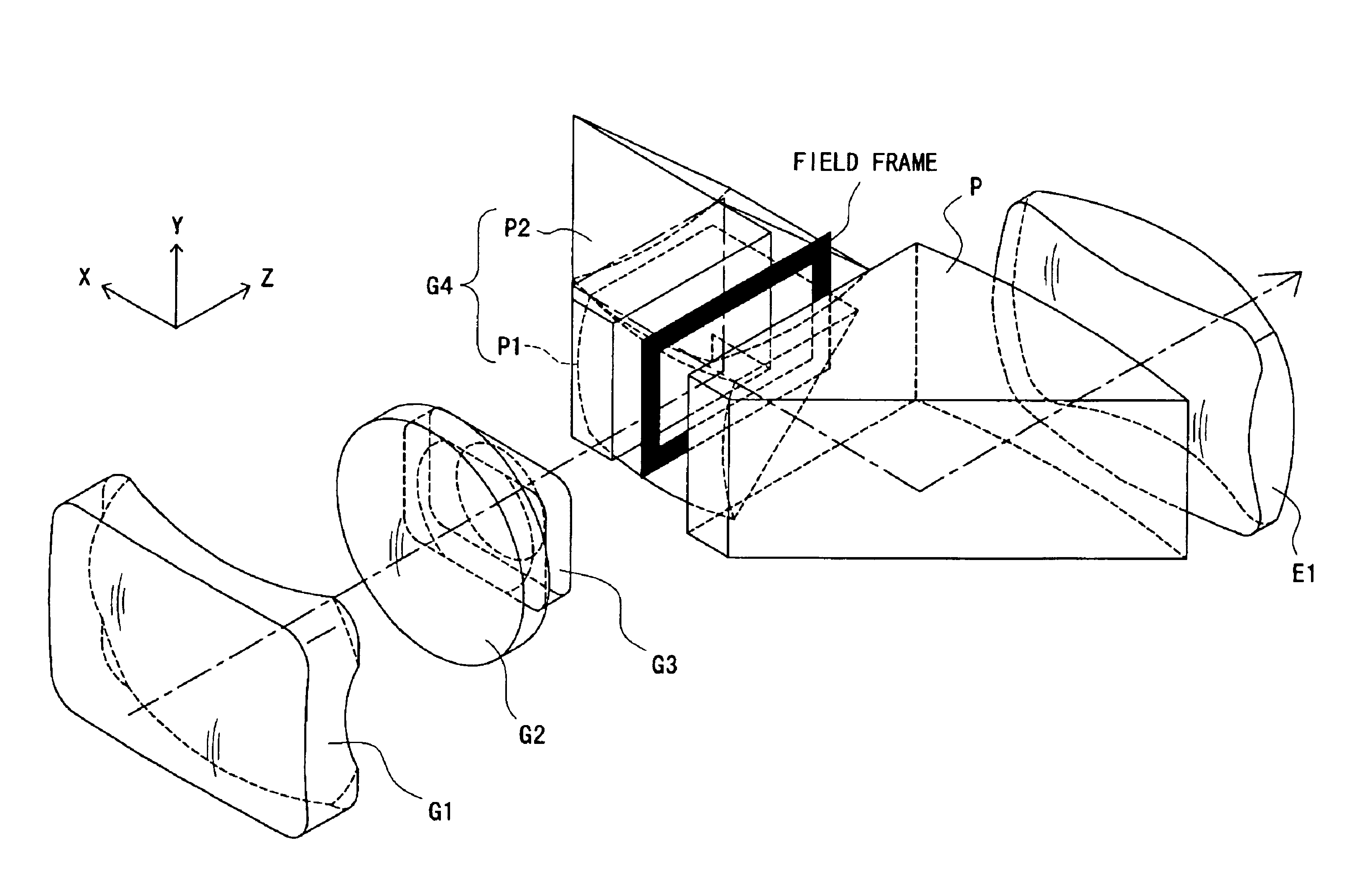
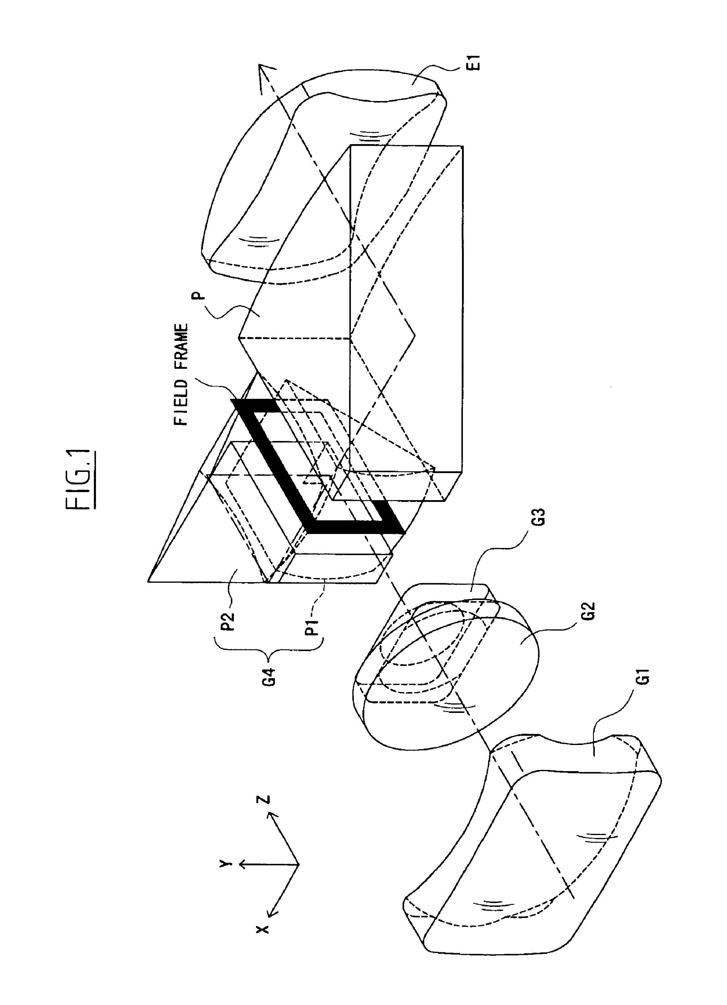
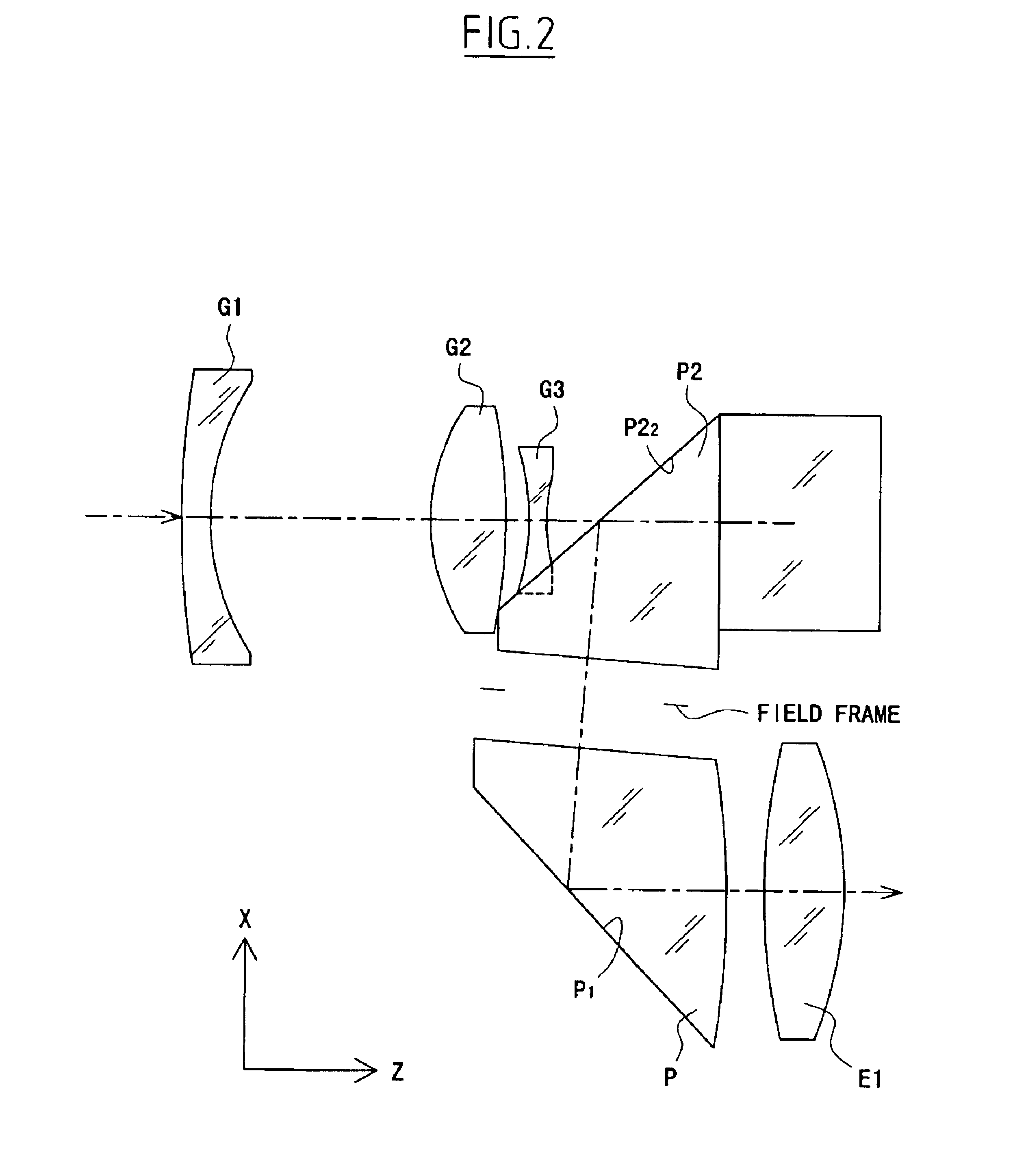
In the real image mode finder optical system of this embodiment, as shown in FIGS. 30A-30D, the objective optical system includes, in order from the object side, a first unit G1 with a negative refracting power, a second unit G2 with a positive refracting power, a third unit G3 with a negative refracting power, and a fourth unit G4 with a positive refracting power, and has a positive refracting power as a whole.

The fourth unit G4 is constructed with two prisms P1 and P2. The eyepiece optical system is constructed with the prism P and the positive lens E1 and has a positive refracting power as a whole.

The image erecting means includes the prisms P1 and P2 and the prism P. In the real image mode finder optical system of the seventh embodiment, the intermediate image formed by the objective optical system is interposed between the prism P2 and the prism P, and the field frame, such as that shown in FIG. 4, is provided in the proximity of its imaging position.

The magnification of the fi...


PUM


Abstract

A real image mode finder optical system is constructed to be independent of a photographing optical system and includes, in order from the object side, an objective optical system with a positive refracting power, a field frame located in the proximity of the imaging position of the objective optical system, and an eyepiece optical system with a positive refracting power. The real image mode finder optical system has an image erecting means, and the focal length of the objective optical system can be made shorter than that of the eyepiece optical system. In this case, the real image mode finder optical system satisfies the following condition:
0.52<mh/fe<1
where mh is the maximum width of the field frame and fe is the focal length of the eyepiece optical system.

Description

BACKGROUND OF THE INVENTION1. Field of the InventionThis invention relates to a real image mode finder optical system suitable for use in a lens shutter camera or an electronic still camera which is constructed so that a photographing optical system is independent of a finder optical system, and in particular, to a real image mode finder optical system which has a large angle of emergence and is best adapted for mounting to a compact camera.2. Description of Related ArtIn general, finders constructed to be independent of photographing optical systems, used in lens shutter cameras, are roughly divided into two classes: virtual image mode finders and real image mode finders.The virtual image mode finder has the advantage that an image erecting optical system is not required, but has the disadvantage that since an entrance pupil is located at the same position as an observer's pupil, the diameter of a front lens must be increased or the area of a visual field is not defined. An Albada ...

Claims


Application Information

Patent Timeline
Patent Type & Authority Patents(United States)
IPC IPC(8): G02B15/177G02B23/14
CPCG02B15/177G02B23/14G02B23/145G02B15/143503
Inventor TOCHIGI, AKIYOSHI
Owner OLYMPUS CORP
Why Eureka
Try Eureka