Fluid treatment system and cleaning apparatus therefor

a treatment system and fluid technology, applied in the field of cleaning equipment, can solve the problems of affecting the cleaning effect, and reducing the efficiency of cleaning liquids, so as to achieve the effect of reducing the leakage of cleaning solution

Inactive Publication Date: 2005-03-08
TROJAN TECH
View PDF14 Cites 29 Cited by
  • Summary
  • Abstract
  • Description
  • Claims
  • Application Information

AI Technical Summary

Benefits of technology

Thus, the present inventors have developed a novel cleaning device for use in a fluid treatment system. The cleaning device contains two “independent” chambers. Specifically, there is provided a cleaning chamber for containing a cleaning solution in contact with an exterior of a radiation source assembly. A second chamber is provided in the cleaning sleeve substantially adjacent the first chamber. The second chamber, in essence, functions as a fluid (typically water) buffer layer between the cleaning chamber and the fluid being treated. Thus, the fluid buffer layer acts to receive small amounts of cleaning solution which may leak from the cleaning chamber thereby obviating or mitigating passage of the cleaning fluid to the fluid being treated.
The cleaning chamber and the chamber defining the fluid buffer layer are relatively “independent” of one another. This may be achieved by using a seal between the two chambers. Since even the highest quality seals are likely to allow some leakage of cleaning fluid, the fluid buffer layer in the second chamber adjacent the cleaning chamber acts to obviate or mitigate alternate leakage of the cleaning fluid into the fluid being treated. This renders the present cleaning system advantageous for use in a clean water application where the fluid being treated is, for example, potable water.
When implemented in a fluid treatment system for clean water applications, it is conventional to dispose the treatment system in a closed pipe containing a pressurized (e.g., 150 psig) flow of water. If the cleaning solution in the cleaning chamber and the fluid in the second chamber acting as the fluid buffer layer are maintained at a pressure lower than the pressure of the fluid flow through the fluid treatment system, there is, in essence, a pressure drop across the region of the fluid flow and the two chambers of the cleaning device. This pressure drop assists in obviating or mitigating leakage of fluid from the cleaning chamber through the second chamber to the fluid being treated.
In a preferred embodiment, the second chamber defining the fluid buffer layer further includes a drain to remove fluid from the second chamber. This further obviates or mitigates leakage of cleaning solution from the cleaning chamber through the second chamber to the fluid being treated.

Problems solved by technology

However, disadvantages exist with the above-described systems.
Depending upon the quality of the fluid which is being treated, the sleeves surrounding the UV lamps periodically become fouled with foreign materials, inhibiting their ability to transmit UV radiation to the fluid.
This required surplus UV capacity adds to the capital expense of installing the treatment system.
Depending on the number of modules which must be serviced for cleaning at one time and the frequency at which they require cleaning, this can also significantly add to the expense of operating and maintaining the treatment system.
Furthermore, this cleaning regimen necessitates relatively high labor costs to attend to the required removal / re-installation of modules and removal / re-filling of cleaning solution in the cleaning vessel.
Still further, such handling of the modules results in an increased risk of damage to or breakage of the lamps in the module.
If the frames are in a closed system (e.g., such as the treatment chamber described in U.S. Pat. No. 5,504,335 (in the name of Maarschalkerweerd and assigned to the assignee of the present invention), the contents of which are hereby incorporated by reference), removal of the frames from the fluid for cleaning is usually impractical.
Cleaning such closed systems suffers from the disadvantages that the treatment system must be stopped while cleaning proceeds and that a large quantity of cleaning solution must be employed to fill the treatment enclosure.
An additional problem exists in that handling large quantities of cleaning fluid is hazardous and disposing of large quantities of used cleaning fluid is difficult and / or expensive.
Of course open flow systems suffer from these two problems, albeit to a lesser degree.
Indeed, it is the belief of the present inventors that, once installed, one of the largest maintenance costs associated with prior art fluid treatment systems is often the cost of cleaning the sleeves about the radiation sources.
Clean water treatment systems present a unique set of challenges since the fluid being treated in the system is a source of potable / drinking water.
If the cleaning system described in the Maarschalkerweerd #2 Patents were implemented in a clean water treatment system, there would be a significant likelihood of leakage of the cleaning solution from the chamber into the fluid being treated.

Method used


Image

  • Fluid treatment system and cleaning apparatus therefor
  • Fluid treatment system and cleaning apparatus therefor
  • Fluid treatment system and cleaning apparatus therefor

Examples


Embodiment Construction

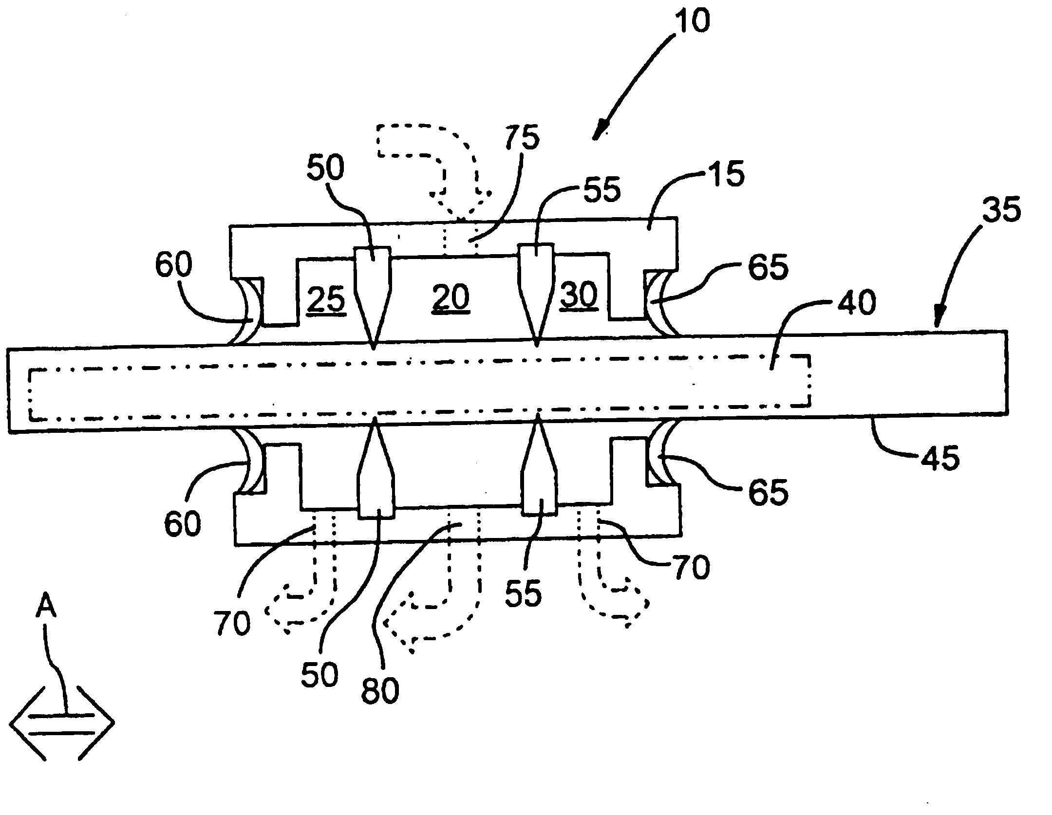
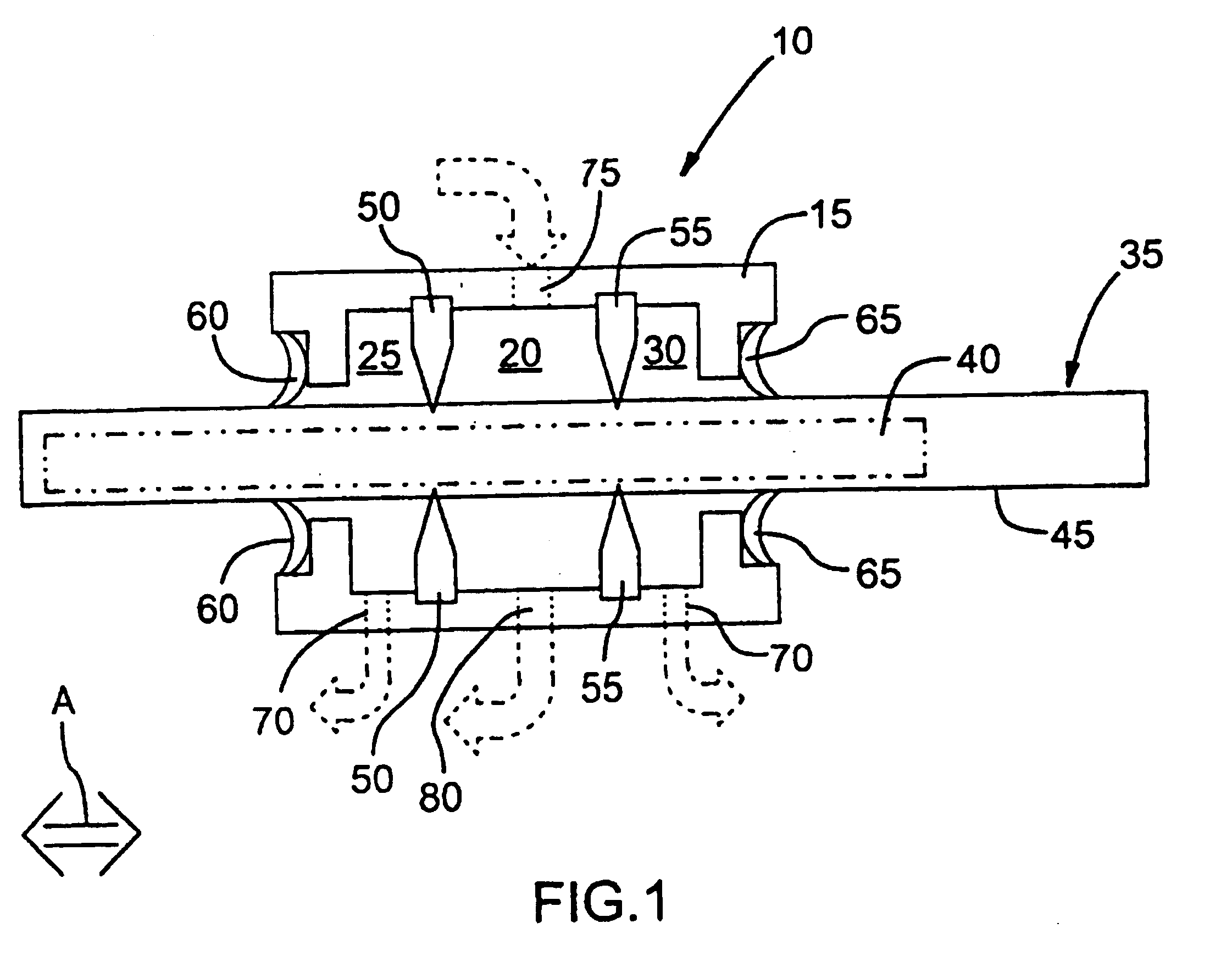
With reference to FIG. 1, there is illustrated a cleaning apparatus 10. Cleaning apparatus 10 comprises a cleaning sleeve 15. Cleaning sleeve 15 comprises a cleaning chamber 20 and a pair of second chambers 25,30. Cleaning sleeve 15 is disposed over a radiation source assembly 35 comprising a radiation source 40 enclosed within a protective sleeve 45.

Cleaning chamber 20 is separated from second chambers 25,30 by a pair of seals 50,55.

Second chambers 25,30 are sealed from the exterior of the cleaning sleeve 15 by a pair of annular seals 60,65. Cleaning sleeve 15 is reversibly movable along the exterior of protective sleeve 45 in the direction of arrow A. The actuation of cleaning sleeve 15 along the exterior of protective sleeve 45 will be described in more detail hereinbelow.

Cleaning sleeve 15 further comprises a drain 70 from each of second chambers 25,30. Drain 70 may be utilized at atmospheric pressure. Ofcourse, the illustrated embodiment could be modified to have a single drain...


PUM

PropertyMeasurementUnit
frequencyaaaaaaaaaa
pressureaaaaaaaaaa
pressure dropaaaaaaaaaa

Abstract

A cleaning apparatus (10) for a radiation source assembly (35) in a fluid treatment system is described. The cleaning apparatus comprise cleaning chamber (20) and a second chamber (25, 30) independent of the cleaning chamber which defines a fluid (typically water) buffer layer to obviate or mitigate cleaning fluid from the cleaning chamber leaking into the fluid being treated. The fluid treatment system is particularly useful for us in clean water applications in which ultraviolet radiation is used to treat the water while having the advantages of in situ cleaning of the radiation source when it becomes fouled.

Description

TECHNICAL FIELDIn one of its aspects, the present invention relates to a cleaning apparatus for use in a fluid treatment system. In another of its aspects, the present invention relates to a fluid treatment system comprising the cleaning apparatus.BACKGROUND ARTFluid treatment systems are known generally in the art.For example, U.S. Pat. Nos. 4,482,809, 4,872,980 and 5,006,244 (all in the name of Maarschalkerweerd and all assigned to the assignee of the present invention and hereinafter referred to as the Maarschalkerweerd #1 Patents), the contents of each of which are hereby incorporated by reference, all describe gravity fed fluid treatment systems which employ ultraviolet (UV) radiation.Such systems include an array of UV lamp frames which include several UV lamps each of which are mounted within sleeves which extend between and are supported by a pair of legs which are attached to a cross-piece. The so-supported sleeves (containing the UV lamps) are immersed into a fluid to be t...

Claims


Application Information

Patent Timeline
Patent Type & Authority Patents(United States)
IPC IPC(8): B01J19/12B08B1/00B08B9/02C02F1/32H05B3/00
CPCB01J19/123B08B1/008H05B3/0052C02F1/325B08B9/023B01J2219/0877C02F2201/324
Inventor DALL'ARMI, VIVIANFANG, GANGLAWRYSHYN, YURILEM, JOSEPHPENHALE, DOUGLAS
Owner TROJAN TECH
Why Eureka
Try Eureka