High-speed rolling contact fatigue testing machine

A technology of contact fatigue and high-speed rolling, which is applied in the field of testing machines, can solve the problems that affect the accuracy of the test results of the test progress, affect the test results of the friction torque of the sample, and cannot realize continuous loading. Small, low-noise effect

Inactive Publication Date: 2013-10-09
YANSHAN UNIV
View PDF10 Cites 18 Cited by
  • Summary
  • Abstract
  • Description
  • Claims
  • Application Information

AI Technical Summary

Problems solved by technology

The loading methods used in the above test machines are mechanical loading or hydraulic loading. Mechanical loading can simulate some simple changing loads but cannot achieve continuous loading. Hydraulic loading is likely to cause environmental pollution and the noise generated will have a certain impact on the acquisition of sensor signals; "A Rolling Bearing Fatigue Life Enhancement Testing Machine" under high-speed and heavy-load conditions, the supporting rolling bearing in the transmission shaft system is used as a companion test piece, which may fail before the tested bearing test piece, affecting the test progress and accuracy of test results; At the same time, the supporting rolling bearing of the shaft system in the "working condition simulation rolling contact fatigue testing machine" produces a large static friction torque during the test, which affects the test results of the friction torque of the sample

Method used


Image

  • High-speed rolling contact fatigue testing machine
  • High-speed rolling contact fatigue testing machine
  • High-speed rolling contact fatigue testing machine

Examples


Embodiment

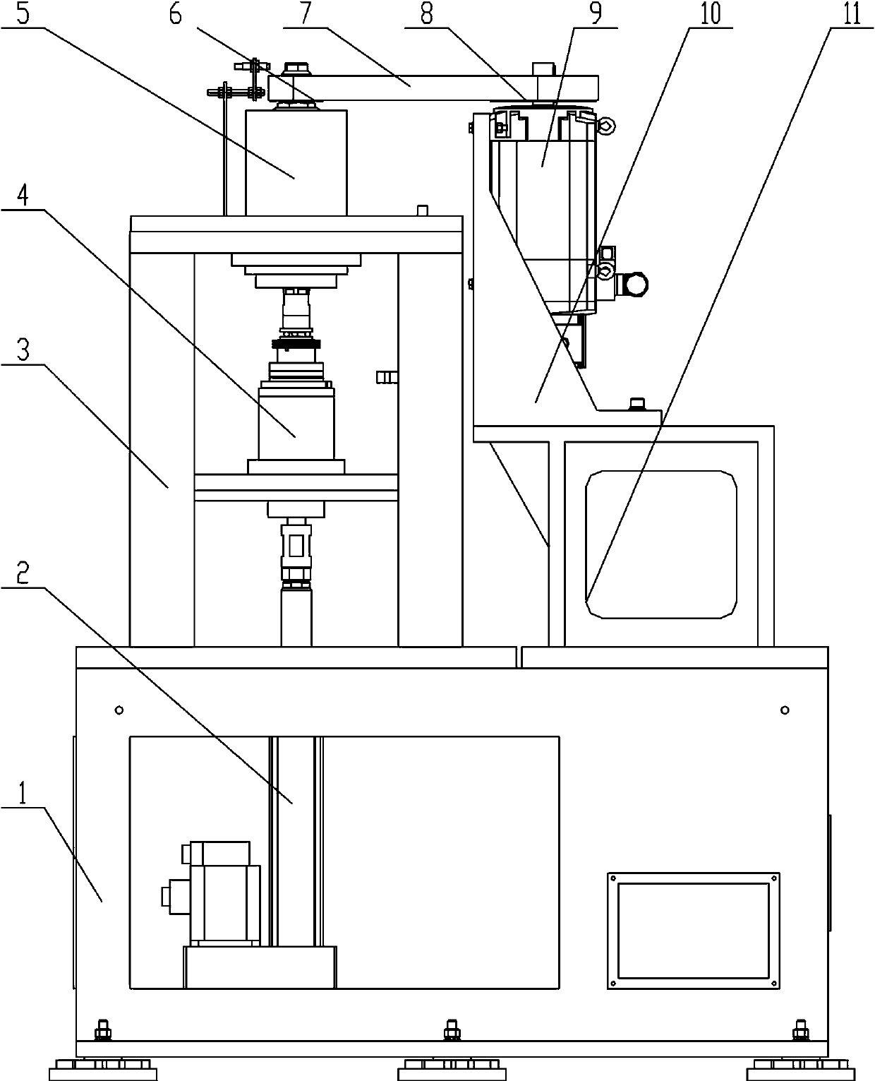
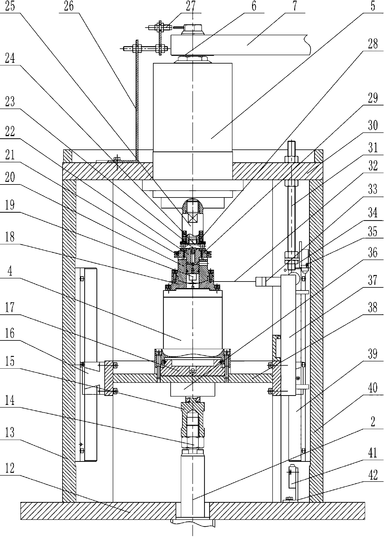
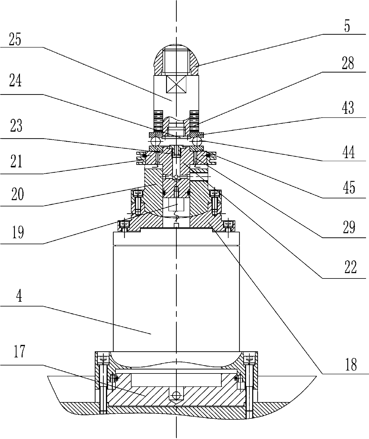
[0022] figure 1 , figure 2 It is a structural schematic diagram of the high-speed rolling contact fatigue testing machine disclosed by the present invention. The frame 3 and the independent motor base 11 are fixed on the base 1, and the motor support 10 is installed on the independent motor base 11. Servomotor 9 is installed on the side of motor support 10, driving pulley 6 is installed on the output shaft of servomotor 9 by taper sleeve, and servomotor 9 is fixed on static pressure main shaft 5 upper ends by driving pulley 6, ribbed belt 7 and Driven belt pulley 8 drive connections. The static pressure main shaft 5 is fixed on the upper beam 30 of the frame 3 through the end flange. The upper end of the transmission mandrel 25 is connected with the lower end of the static pressure main shaft 5 through threads, the inner ring of the ceramic heat insulating sleeve 28 is connected with the transmission mandrel 25 through clearance fit, and the shaft ring 43 of the thrust bea...


PUM


Abstract

The invention discloses a high-speed rolling contact fatigue testing machine. The high-speed rolling contact fatigue testing machine is characterized in that a driving pulley (6) arranged on the upper end of the output shaft of a servo motor (9) is in transmission connection with a driven pulley (8) arranged on the upper end of a static pressure main shaft (5), and the static pressure main shaft (5) is fixed on an upper beam (30) arranged on a rack (3); a servo electric cylinder (2) is connected with a pressure sensor (36) fixed on the lower surface of a moving beam through a connecting piece (15) of the pressure sensor; the upper end of a hydraulic supporting platform (4) is fixed on a sphere base lower part (18), a lower test specimen base (21) is connected with a sphere base upper part (20), and the lower test specimen base (21) is connected with a test specimen base ring (45) in a clearance fit mode. The high-speed rolling contact fatigue testing machine provided by the invention has the advantages that the rolling contact of a bearing material under a high speed and heavy load working condition is simulated, the key parameter of rolling contact fatigue of a testing material can realize accurate detection, and finally, the data support is provided for evaluating the rolling contact fatigue property of the bearing material.

Description

technical field [0001] The invention relates to a testing machine for evaluating rolling contact fatigue performance of bearing materials under high-speed and heavy-load working conditions. Background technique [0002] As a widely used mechanical basic part, the quality of rolling bearings directly affects the performance of the whole machine. At present, problems such as fatigue pitting, plastic deformation and wear of bearings restrict the development of high-speed and heavy-duty machinery. It is imperative to develop high-performance bearing materials to meet the increasingly high-speed requirements of rotating parts. Contact fatigue is one of the main failure modes of rolling bearings, and it has the characteristics of low stress and no macroscopic deformation. Contact fatigue is more dangerous than static damage. Simulating the actual working conditions of bearings, accurately predicting the bearing capacity and life of bearings under specific conditions, and then gi...

Claims


Application Information

Patent Timeline
Patent Type & Authority Applications(China)
IPC IPC(8): G01N19/00
Inventor 胡占齐杨育林齐效文黄茹楠王少伟
Owner YANSHAN UNIV
Why Eureka
Try Eureka