Electric power steering control apparatus

Active Publication Date: 2005-03-08
MITSUBISHI ELECTRIC CORP
View PDF12 Cites 50 Cited by
  • Summary
  • Abstract
  • Description
  • Claims
  • Application Information

AI Technical Summary

Benefits of technology

The present invention has been made to solve the above problems, and an object of the invention is therefore to provide an electric power steering control apparatus capable of increasing the accuracy of est

Problems solved by technology

However, the conventional technique of arranging the time constants of the low-pass filters in accordance with only the steering speed has a problem that the accuracy of estimation of road surface reaction torque is lowered as the vehicle spee

Method used


Image

  • Electric power steering control apparatus
  • Electric power steering control apparatus
  • Electric power steering control apparatus

Examples


embodiment 1

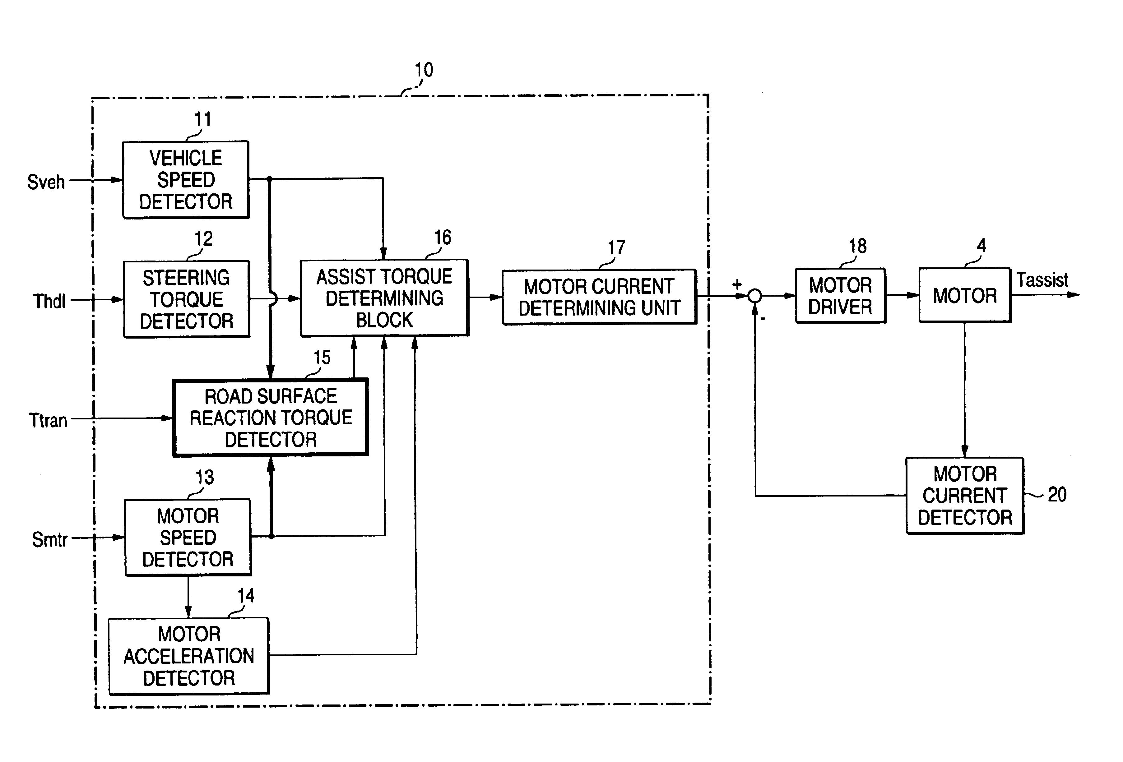
FIG. 1 is a schematic diagram showing an electric power steering control apparatus according to a first embodiment of the present invention.

In FIG. 1, reference numeral 1 denotes a steering wheel of an automobile that is manipulated by a driver. The steering wheel 1 is coupled to a steering shaft 1A. Reference numeral 2 denotes tires that are attached to both ends of an axle 2A of the automobile. The steering shaft 1A is coupled to the axle 2A so as to steer it. Reference numeral 3 denotes a torque sensor that is provided in a steering torque transmission mechanism from the steering wheel 1 to the tires 2, for example, attached to the steering shaft 1A. The torque sensor 3 detects a steering torque that is generated by a steering manipulation of the driver. Reference numeral 4 denotes an EPS (electric power steering) motor that is provided in the steering torque transmission mechanism from the steering wheel 1 to the tires 2, for example, attached to the steering shaft 1A so as to a...

embodiment 2

FIG. 9 is a block diagram showing the configuration of an electric power steering control apparatus according to a second embodiment of the invention. A block 10A enclosed by dot-dashed lines in FIG. 9 is a block for calculating a target value of the drive current Imtr of the motor 4. In the second embodiment, a road surface reaction torque detector 15A is used instead of the road surface reaction torque detector 15 shown in FIGS. 4 and 5. FIG. 10 is a block diagram showing the configuration of the road surface reaction torque detector 15A of the electric power steering control apparatus according to the second embodiment of the invention. A block enclosed by dot-dashed lines corresponds to the road surface reaction torque detector 15A.

In FIG. 9, whereas the road surface reaction torque detector 15A is used, the sections 11-20 are the same as in FIG. 4. As shown in FIG. 10, the road surface reaction torque detector 15A has blocks 21A, 22, 23 and 24. The blocks 22-24 are same as in F...

embodiment 3

FIG. 12 is a characteristic diagram showing a relationship between the road surface reaction torque and the steering angle in an electric power steering control apparatus according to a third embodiment of the invention. In FIG. 12, the vertical axis represents the torque (N·m) and the horizontal axis represents the time (s). Characteristic E is road surface reaction torque Talign (divided by 50), characteristic F is a steering angle θhdl, and characteristic G is the steering shaft speed. The steering shaft speed is proportional to the motor rotation speed.

FIG. 13 is a block diagram showing the configuration of a road surface reaction torque detector 15B of the electric power steering control apparatus according to the third embodiment of the invention. A block enclosed by dot-dashed lines corresponds to the road surface reaction torque detector 15B.

In FIG. 13, the blocks 21A, 22, 23 and 24 are the same as shown in FIG. 10. Reference characters J and K denote operators. The operator...


PUM


Abstract

A road surface reaction torque detector has a low-pass filter element whose time constant is determined in accordance with a vehicle speed that is detected by a vehicle steed detector and a motor rotation speed that is detected by a motor rotation speed detector. A road surface reaction torque estimation value is obtained in such a manner that the road surface reaction torque detector performs low-pass filter processing on steering shaft reaction torque signal that is outputted by a steering shaft reaction torque signal outputting means. As a result, an accuracy of estimation of road surface reaction torque is improved.

Description

BACKGROUND OF THE INVENTION1. Field of the InventionThe present invention relates to an electric power steering control apparatus for controlling an electric motor device that generates assist torque for assisting steering torque of an automobile driver.2. Description of the Related ArtAmong conventional electric power steering control apparatus is one disclosed in JP-A-2001-239951 in which one or more stages of first-order low-pass filters are formed to estimate road surface reaction torque and the time constants of the low-pass filters are arranged in accordance with the steering speed. JP-A-2001-122146 discloses an electric power steering control apparatus in which the time constant of a low-pass filter is arranged in accordance with the vehicle speed.However, the conventional technique of arranging the time constants of the low-pass filters in accordance with only the steering speed has a problem that the accuracy of estimation of road surface reaction torque is lowered as the v...

Claims


Application Information

Patent Timeline
IPC IPC(8): B62D5/04B62D6/00
CPCB62D5/0463B62D6/008B62D5/0466
Inventor TANAKA, HIDEYUKIKURISHIGE, MASAHIKOINOUE, NORIYUKITSUTSUMI, KAZUMICHIOHTAGAKI, SHIGEKI
Owner MITSUBISHI ELECTRIC CORP
Why Eureka
Try Eureka