Lubricant injector assembly

a technology of injectors and lubricants, which is applied in the direction of manual lubrication, machines/engines, distribution equipment, etc., can solve the problems of slow venting and recharging of injectors, and achieve the effects of reducing the venting and recharging time, improving the system performance, and fast venting

Inactive Publication Date: 2005-03-08
LINCOLN INDUSTRIES CORP
View PDF28 Cites 11 Cited by
  • Summary
  • Abstract
  • Description
  • Claims
  • Application Information

AI Technical Summary

Benefits of technology

Among the several objects of the invention may be noted the provision of a lubricant injector which, while requiring venting for recharging, vents substantially faster than prior injectors such as the SL-1 and SL-32 injectors, and a method of operation of the injector bringing about the faster venting; the provision of such an injector, the construction and the manufacture of which are no more involved than the construction and manufacture of prior injectors such as the SL-1 and SL-32 injectors; the provision of a centralized lubrication system which may include prior injectors such as the SL-1 and SL-32 injectors, wherein all injectors, including said prior injectors, vent substantially faster t

Problems solved by technology

While these prior injectors have been quite satisfactory in many lubrication system installations, they have the characteristic of being slow to vent for recharging of the injec

Method used


Image

  • Lubricant injector assembly
  • Lubricant injector assembly
  • Lubricant injector assembly

Examples


Embodiment Construction

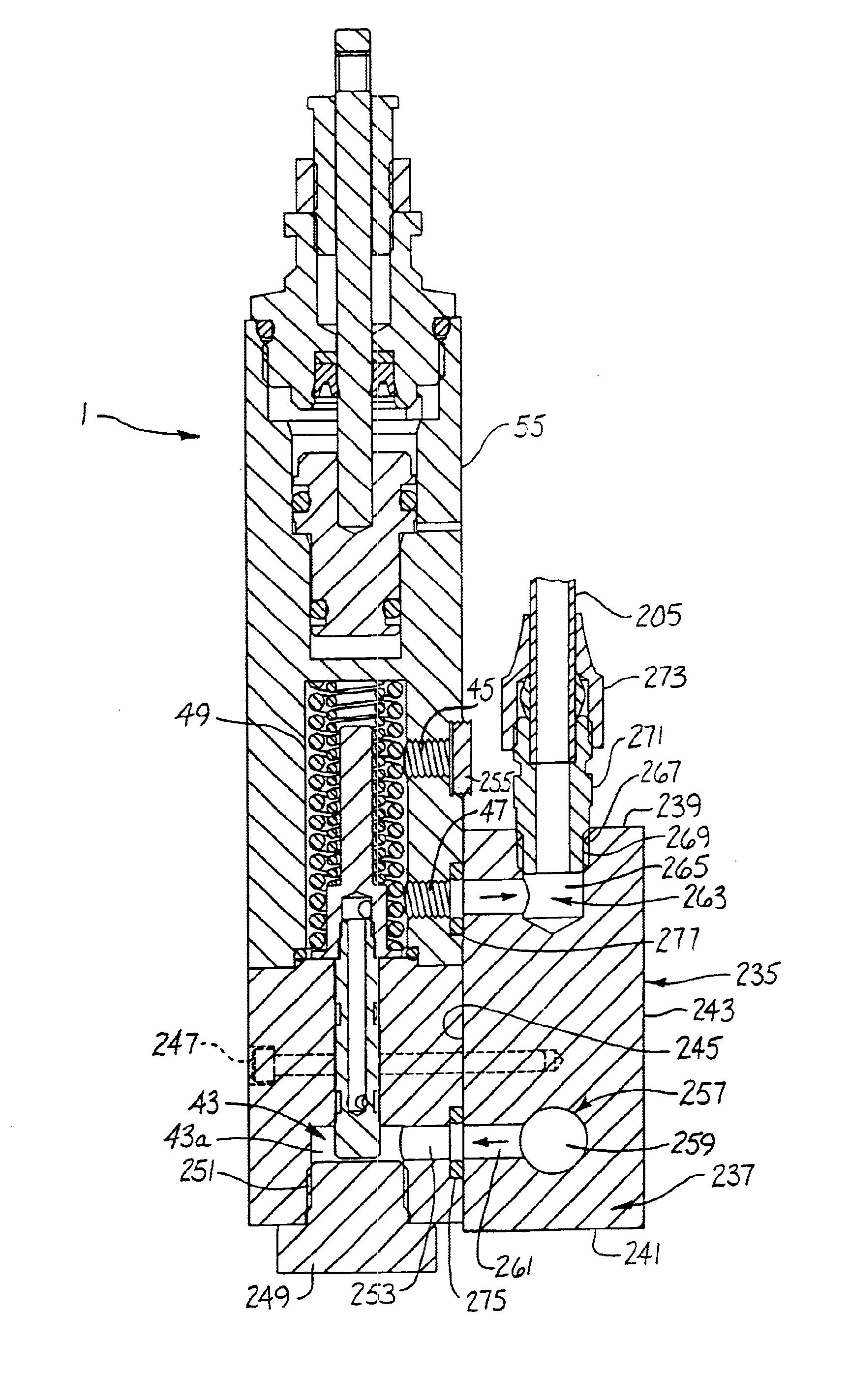
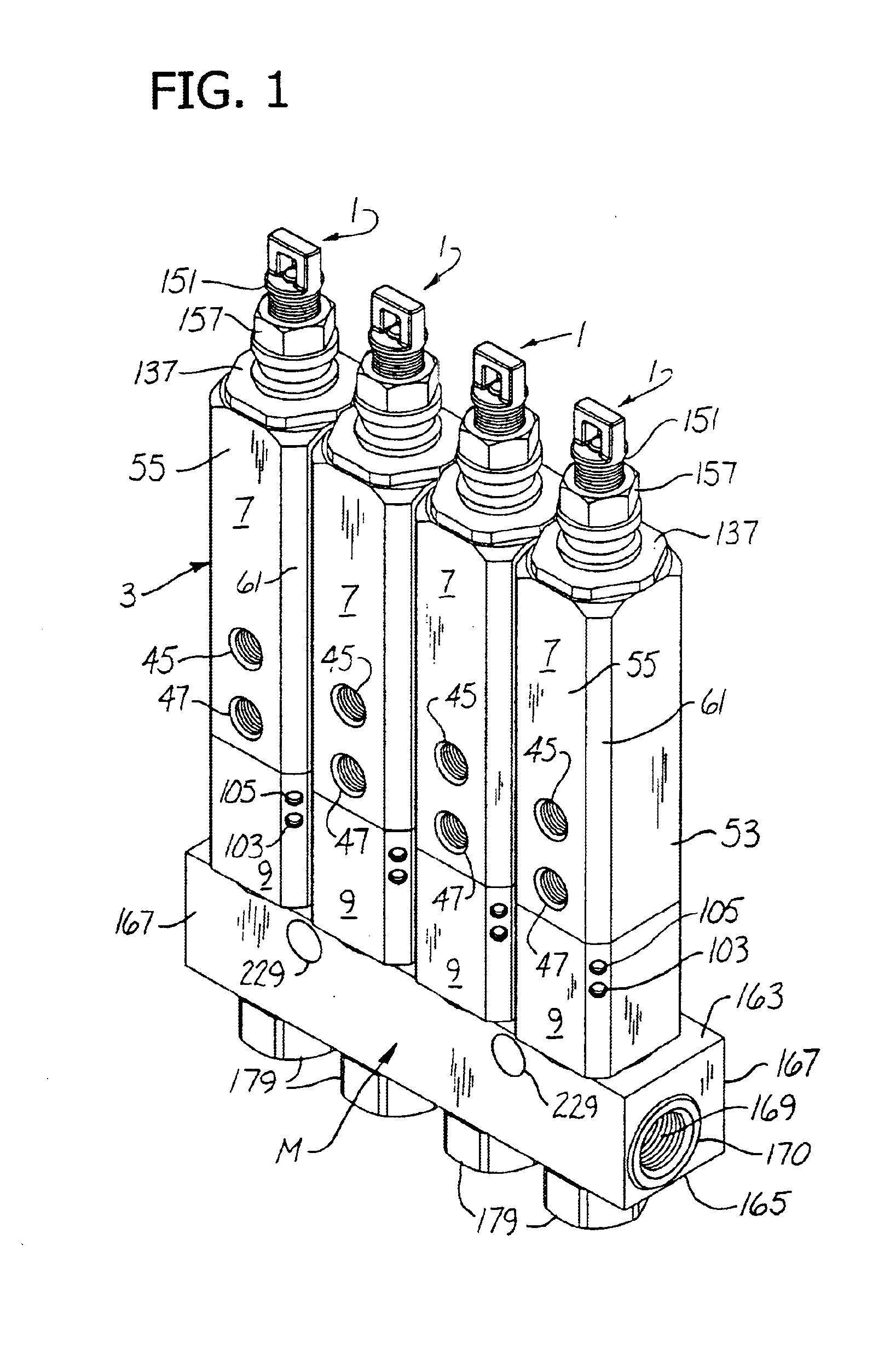
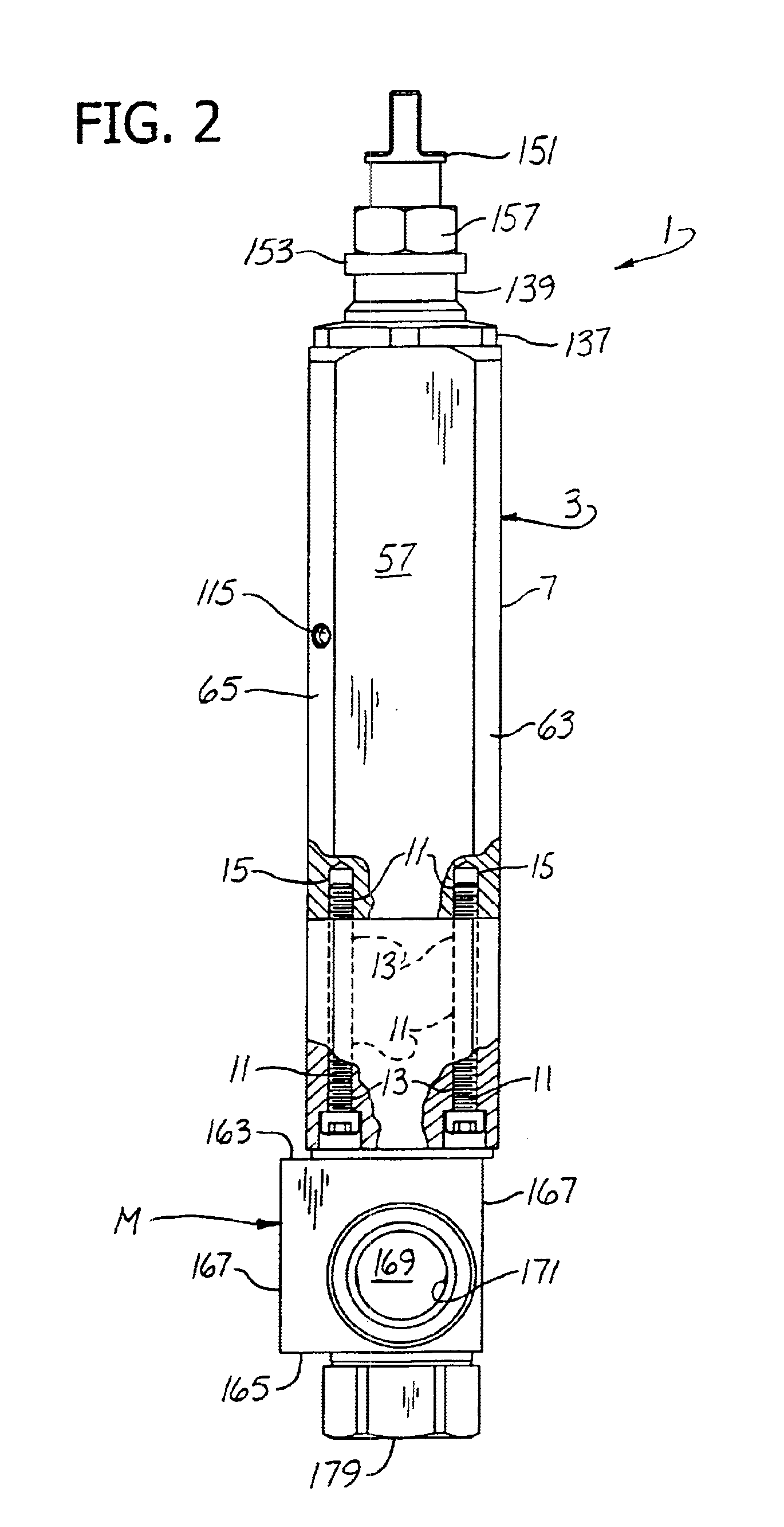
Referring to FIG. 1 of the drawings, there is shown a bank of injectors 1 of this invention (four being shown) on a manifold M for delivery of lubricant under pressure to and venting of lubricant pressure from the injectors. Each injector 1 comprises an elongate body 3 having a differential cylinder 5 therein (see FIGS. 4-7) on its longitudinal axis A adjacent one end of the body (its upper end as shown). In the particular embodiment shown, the body 3 is a two-piece body, comprising an upper part 7 surmounting a lower part 9 fastened together by relatively long screws 11 (see FIGS. 2 and 10) extending up through holes 13 in the lower part threaded at their upper ends in tapped holes 15 in the lower end of the upper part. The upper part 7 of the body has a bore 17 and first and second counterbores 19 and 21 extending in (down as shown in FIG. 4A) from the upper end thereof on axis A, the bore 17 and first counterbore 19 (having a larger diameter and thus a larger cross-sectional area...


PUM


Abstract

A lubricant injector having a measuring chamber, venting of the injector involving transmission of lubricant from its inlet to the measuring chamber, a method of operation of the injector involving such transmission, systems embodying one or more of such injectors, improving the performance of existing systems by use of one or more such injectors, an injector/connector assembly, and an injector sealing assembly.

Description

BACKGROUND OF THE INVENTIONThis invention relates to lubricant injection, more particularly a lubricant injector, a method of operation thereof, a lubricant injector system embodying the injector of the invention, a method of improving the performance of existing lubricant injector systems, and an injector / connector assembly.The invention is especially concerned with a lubricant injector for use in a single-line lubrication system, a method of operation of the injector, a single-line system embodying one or more lubricant injectors, a method of improving the performance of existing systems, and an injector / connector assembly. The term “connector” as used herein means the structure, such as a manifold or a single-outlet means for connecting a plurality of injectors or a single injector with a lubricant supply line.The invention involves a major improvement in an extensive series of injectors, lubricant injector systems and injector / connector assemblies developed by predecessors of th...

Claims


Application Information

Patent Timeline
IPC IPC(8): F16N25/00F16N25/02F16N27/00F16N7/38
CPCF16N27/00F16N25/02
Inventor CONLEY, PAUL G.ARENS, THOMAS M.
Owner LINCOLN INDUSTRIES CORP
Why Eureka
Try Eureka