Aerodynamic profile with an adjustable flap

a technology of adjustable flaps and aerodynamic profiles, which is applied in the direction of fuselages, sustainable transportation, transportation and packaging, etc., can solve the problems of not being able to achieve the effect of technically ensuring, not being able to meet or exceed the expected rising demands of passenger planes, and not being able to achieve the effect of meeting the needs of passenger planes, reducing weight, and facilitating flap fastening

Inactive Publication Date: 2005-03-08
AIRBUS OPERATIONS GMBH
View PDF12 Cites 19 Cited by
  • Summary
  • Abstract
  • Description
  • Claims
  • Application Information

AI Technical Summary

Benefits of technology

[0017]Furthermore, recesses are advantageously provided in the pressure-side covering skin. These recesses significantly facilitate fastening of the flap on the pressure-side covering skin. In this case, it is expedient to introduce corresponding fastening areas of the fastening elements into the recesses and to mount them by gluing and/or riveting on the pressure-side covering skin.
[0018]Advantageously, connection elements are arranged between the suction-side and the pressure-side covering skin. These connection elements are constructed in a rib shape and are arranged extending in the flow direction. As a result, a monolithic construction is achieved, which is advantageous with respect to reducing weight.
[0019]A connection profile is expediently arranged between the spaced covering skins. By way of the connection profile, the rearward profile area can be mounted on the forward profile area. In this manner, the rearward profile area can be easi...

Problems solved by technology

However, with a view to future applications, it is problematic that, with previously known control flaps, expected rising demands on passenger planes, as a result of an increase in air traffic, will not be met or will not be met sufficiently effectively.
So far, it has only been possible to technically ensure the requir...

Method used


Image

  • Aerodynamic profile with an adjustable flap
  • Aerodynamic profile with an adjustable flap
  • Aerodynamic profile with an adjustable flap

Examples


first embodiment

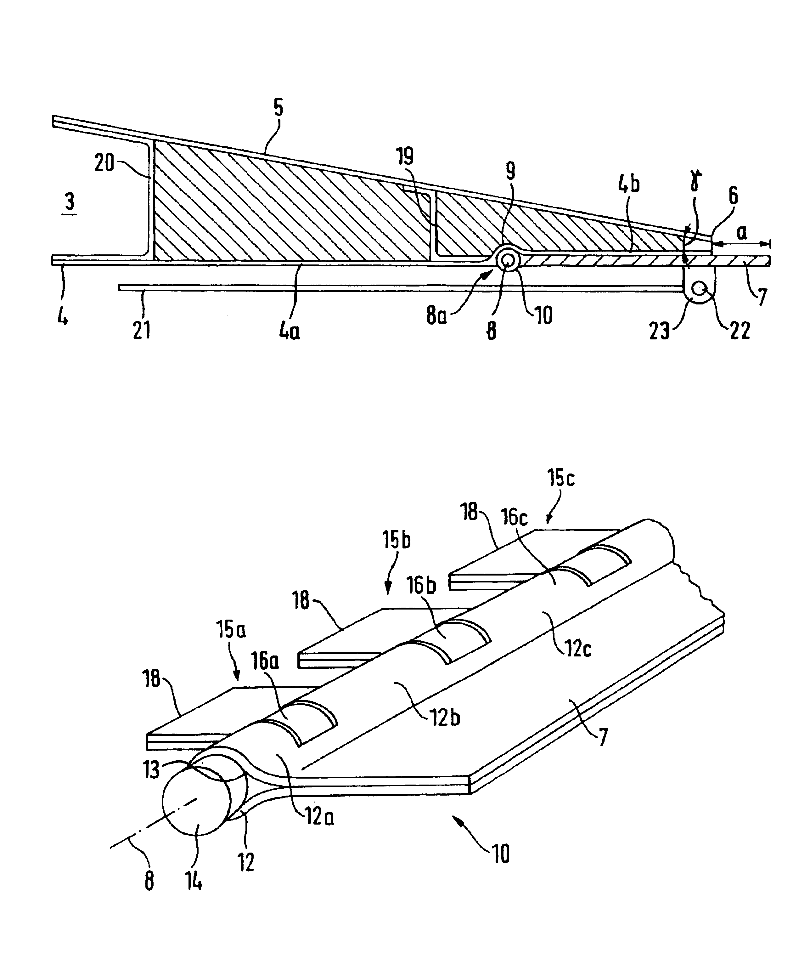
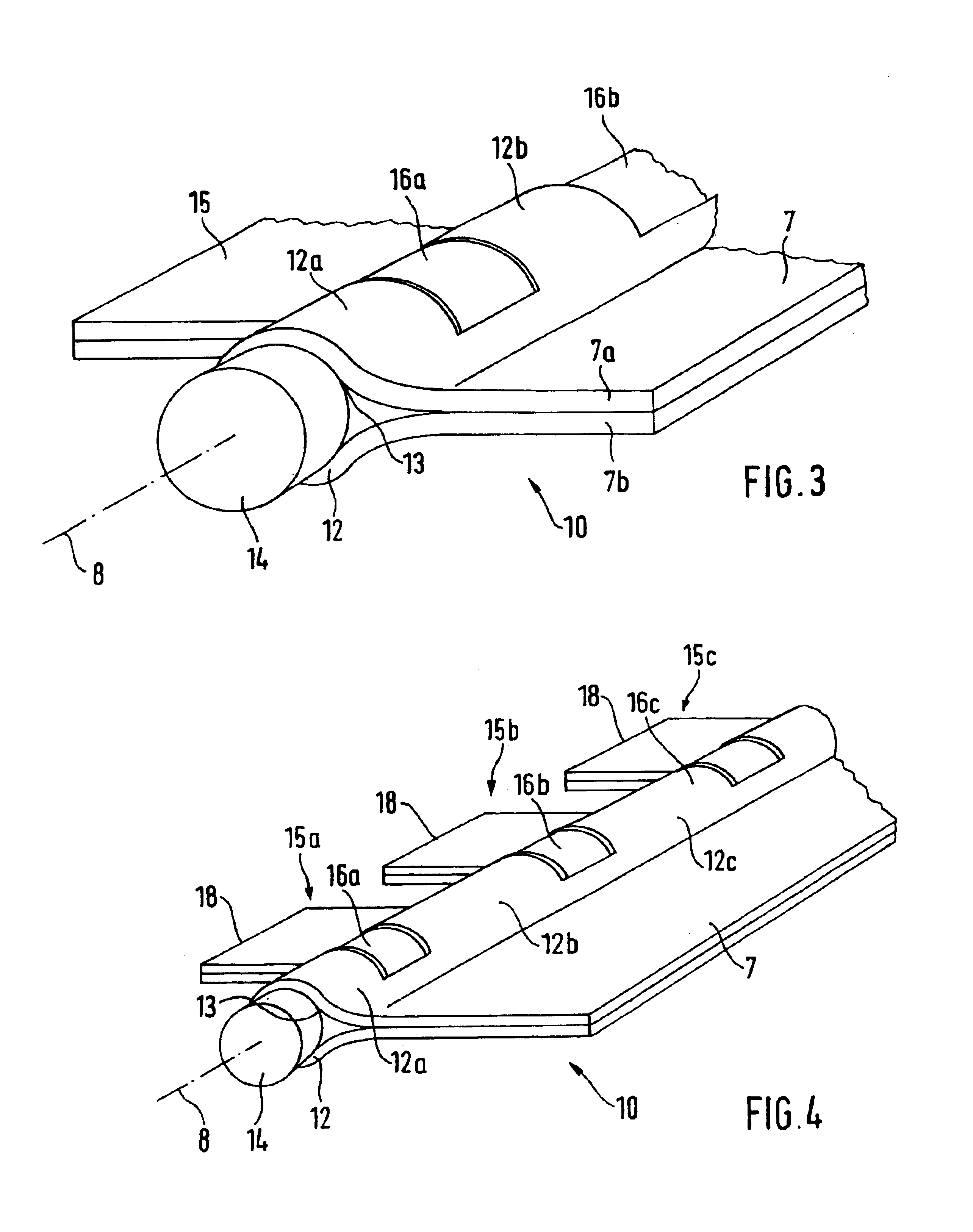
[0035] the flap 7 is of a so-called prepreg material. It is known that the term “prepreg” indicates a preimpregnated fiber arrangement. The flap 7 has a plurality of prepreg strips which are laminated for forming a loop area 12 to the symmetry plane of the flap 7 and are then folded together (FIG. 3). Thus, the thickness of the flap 7 is composed of the sum of the respective thicknesses of the symmetrical partial layers which, in FIG. 3, have the reference numbers 7a and 7b respectively. As a result of the folding along the symmetry plane, the loop area 12, which takes over the function of the flap bearing, is formed. Furthermore, a sliding material 13 (such as a PTFE liner) is arranged in the loop area 12 so that the torsion bar 14 introduced into the loop area is supported as free of friction as possible and thereby reduces the wear characteristics. In FIG. 3, the sliding material 13 is situated on the torsion bar 14.

[0036]The flap 7 made of a prepreg material forms the first part...

second embodiment

[0039] the flap with an integrated hinge connection 10 can be produced by way of a conventional textile technology method. In this embodiment, the flap 7 has two different multiaxial arrangements, specifically, a unidirectionally as well as a multidirectionally reinforced arrangement, preferably a CFK arrangement. The layers are placed above one another corresponding to the thickness of the flap and are sewn together, the unidirectional arrangement being arranged in the loop area 12. This causes a three-dimensional reinforcement of the flap 7 in the loop area 12. In addition, by way of such an arrangement, delamination of the flap 7 in the symmetry plane starting from the loop area 12 is avoided. As in the case of the above discussed prepreg variant, a sliding material, such as a PTFE liner, is situated in the loop area 12. Here, the inside diameter of the loop area 12 is also defined by the diameter of a shaping bar which is removed after resin injection. The sliding material 13, i...


PUM


Abstract

An aerodynamic profile has an adjustable flap, which has a forward profile area as well as a rearward profile area situated in the downward current, bounded by a pressure-side covering skin as well as a suction-side covering skin. The pressure-side and suction-side covering skins converge in the rearward profile area at a trailing profile edge. In the rearward profile area on the underside of the pressure-side covering skin, a flap is swivellably disposed such that, in the inoperative condition, the flap, pointing in the flow direction, rests against the contour of the pressure-side covering skin and, in the deflected condition, the flap encloses an angle with the pressure-side covering skin. An airtight hinge connection is integrated in the flap so that, on the side of the flap protected from the wind, a turbulence system which improves the flow conditions is formed.

Description

[0002]This application claims the priority of German application 101 56 733.2, filed Nov. 19, 2001, the disclosure of which is expressly incorporated by reference herein.BACKGROUND AND SUMMARY OF THE INVENTION[0003]The present invention relates to an aerodynamic profile with an adjustable flap, having a forward profile area as well as a rearward profile area situated in a downward current, bounded by pressure-side and suction-side covering skins, the pressure-side covering skin and the suction-side covering skin converging, in the rearward profile area, at a trailing profile edge.[0004]Such aerodynamic or lifting-force-generating profiles are typically lifting surfaces and rotor blades on the trailing edges of which landing or control flaps are arranged. As a result of an up and down movement of such a flap, an aerodynamic control effect is caused in a known manner. This is required particularly because of the different aerodynamic requirements during take-off and landing so that it...

Claims


Application Information

Patent Timeline
IPC IPC(8): B64C3/00B64C3/50
CPCB64C3/50Y02T50/145Y02T50/10
Inventor GESSLER, ANDREASHANSEN, HEINZHAVAR, TAMASHOROSCHENKOFF, ALEXANDER
Owner AIRBUS OPERATIONS GMBH
Why Eureka
Try Eureka